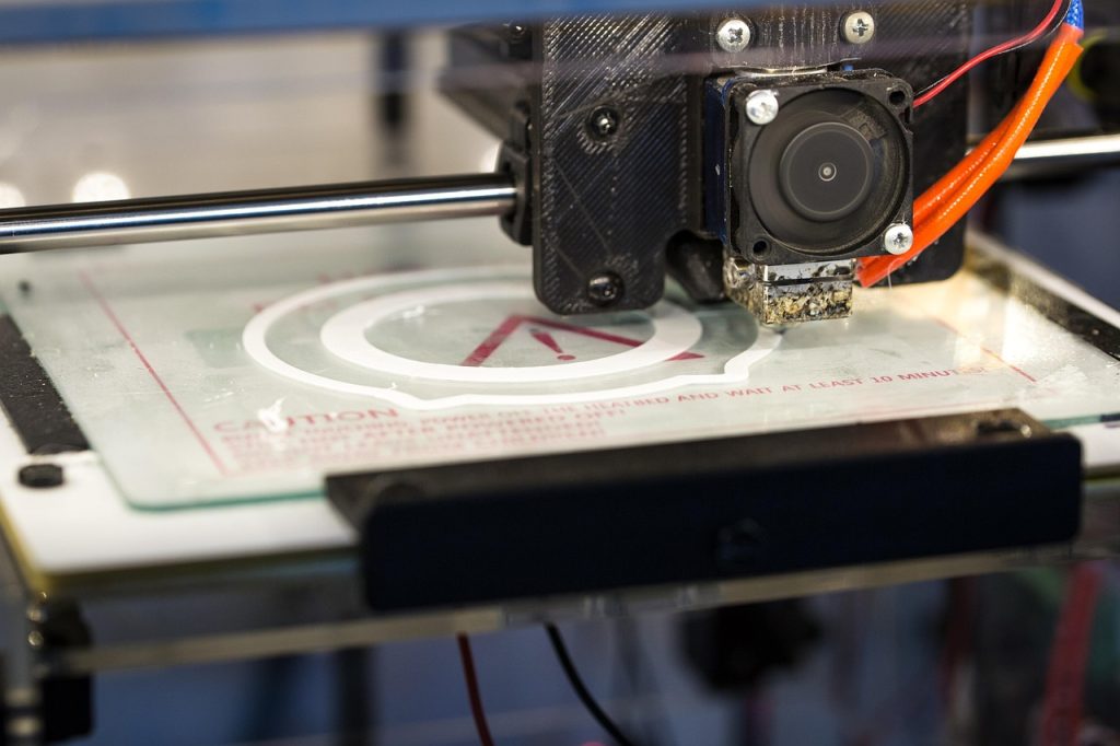
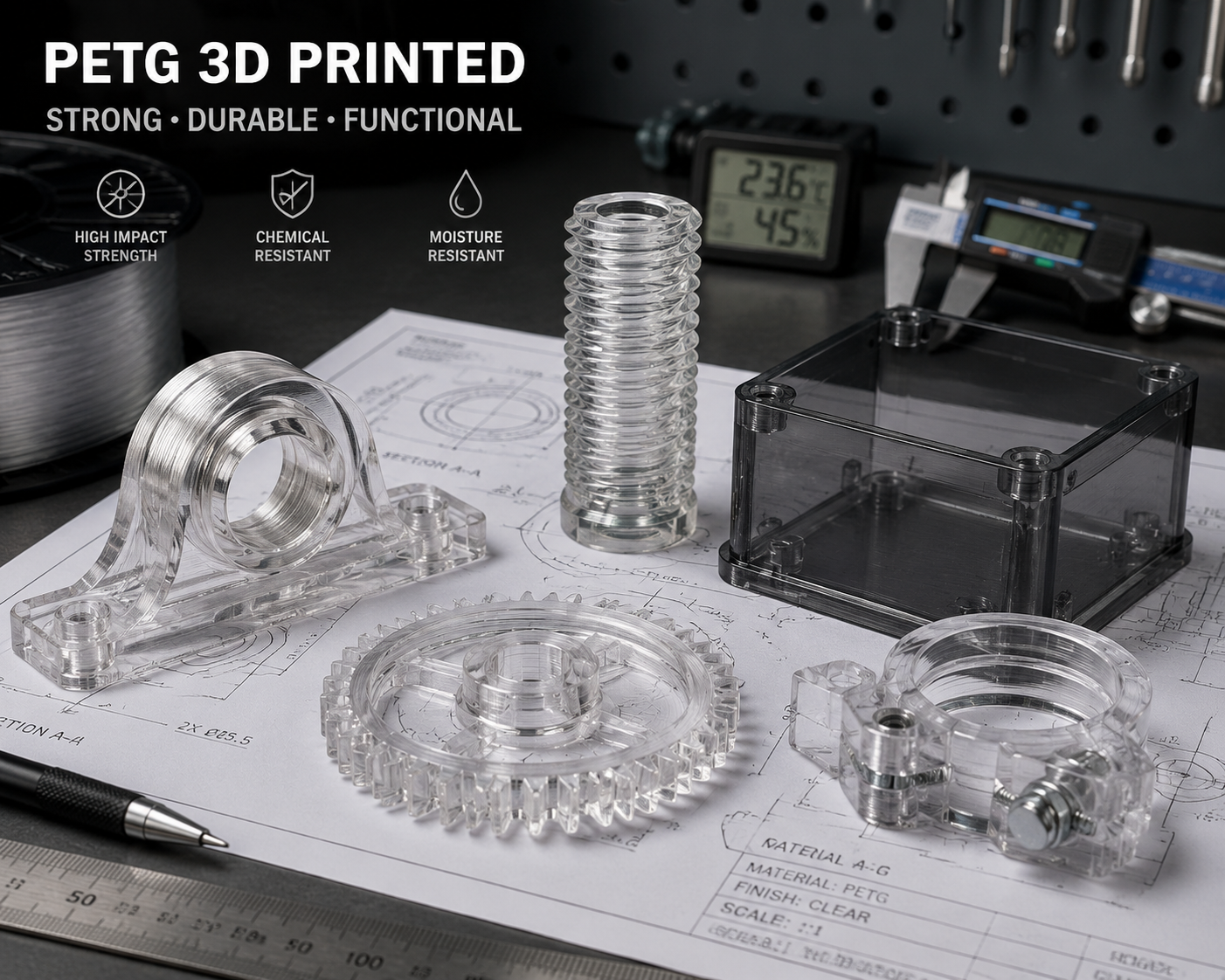
PETGの3Dプリントは、PLAと同じように扱うのではなく、温度、冷却、湿度管理のバランスを適切に取ることが最も効果的です。ポリエチレンテレフタレート・グリコール変性(PETG)は、まさにその中間に位置するため、「どのフィラメントを使えばいいですか?」と尋ねる人にとって、デフォルトの推奨素材となっています。 グリコール改質により、標準的なPETを脆くして印刷不能にする結晶化が抑制されるため、PLAとほぼ同等の印刷しやすさと、ABSに匹敵するほどの強靭さを兼ね備え、さらにどちらの素材にもない耐薬品性と透明性を兼ね備えた材料となっています。まず全体的なトレードオフの観点を知りたい場合は、当社の PLA・PETG・ABSの比較 最も迅速な材料選定の枠組みを提示している。.
PETGは、機能的なFDMプリントの主力素材として、ひっそりとその地位を確立してきました。プリンター部品(Voron製プリンターのプリント部品はすべてPETG製です)、機械用ブラケット、治具、およびPLAの脆さが許容できない一方で、ABSをプリントする手間をかける理由がないあらゆる用途において、PETGは市場を席巻しています。 PETGの具体的な特性、特有の挙動、最適な設定を理解することで、機能的なプリント作業の大部分に対応できる素材の真価を引き出すことができます。.
化学的メカニズム:グリコール修飾が実際にどのような働きをするのか
ペットボトルや食品包装に使用される標準的なPETは、半結晶性高分子です。溶融状態から冷却されると、PETの鎖は規則的な結晶領域を形成します。これが、PETボトルのプリフォームが射出成形後は透明であるものの、延伸されると不透明になる理由です(ひずみ誘起結晶化)。 3Dプリントにおける問題は、結晶化によって材料が脆くなることです。結晶領域は応力集中点として機能し、鎖の運動によるエネルギーの散逸を妨げてしまうからです。.
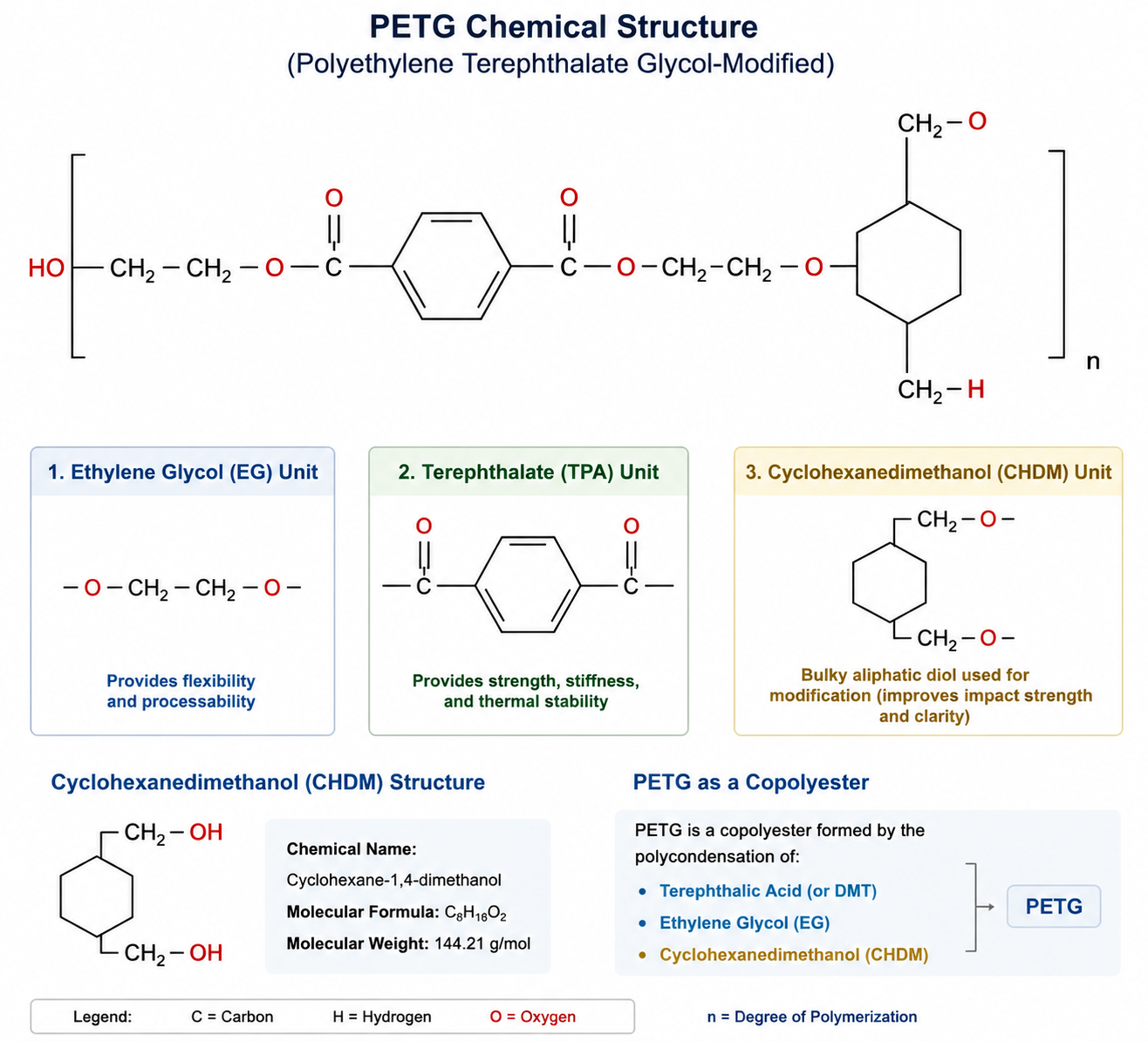
PETGにおけるグリコール改質では、エチレングリコールモノマーの一部がシクロヘキサンジメタノール(CHDM)に置き換えられます。CHDMはより体積の大きいグリコールであり、鎖の配列を乱します。CHDM単位により結晶化が完全に抑制されるため、PETGは完全な非晶質となり、冷却後も強靭さと透明性を維持します。 その代償として、ガラス転移温度はPETの約80°CからPETGでも約80°Cへと低下し(Tgは類似しているが、結晶化挙動は排除される)、また鎖の充填密度が低下するため、引張弾性率もわずかに低下する。.
この非晶質という性質は、PETGのプリント挙動を説明するものでもあります。結晶化を気にする必要がないため、PETGは脆くなることなく比較的速く冷却することができます。そのため、ABSとは異なり、密閉環境を必要とせず、パーツ冷却ファンを活用できるのです。 また、グリコールによる改質により、PETGはPLAよりも耐薬品性に優れています。これは、主鎖に含まれる芳香族テレフタル酸基が、PLAのエステル結合を攻撃する多くの溶剤、油、弱酸に対する耐性を提供するためです。.
| プロパティ | PETG | PLA | ABS | PC |
|---|---|---|---|---|
| 引張強度 | 50~55 MPa | 50-60 | 35-45 | 60-70 |
| 衝撃強度(アイゾット) | 80~110 J/m | 30-50 | 200-400 | 600-850 |
| 曲げ弾性率 | 2.0~2.2 GPa | 3.0-3.5 | 2.0-2.5 | 2.3-2.5 |
| ガラス転移温度(Tg) | 約80°C | 約60°C | 約105°C | 約145°C |
| 破断伸度 | 15-25% | 5-10% | 10-25% | 50-120% |
| 密度 | 1.27 g/cm³ | 1.24 | 1.04 | 1.20 |
| 印刷適性 | 易~中級 | とっても簡単 | 難しい | 非常に難しい |
| 同封必須 | いいえ | いいえ | はい | はい |
プリンターの要件:PETGに必要なもの
PETGはハードウェアへの要求が極めて緩やかです。全金属製のホットエンドが推奨されますが、必ずしも必須というわけではありません。PETGの印刷温度は230~250°Cであり、これはPTFEライニングのホットエンドの上限温度ですが、250~260°Cという劣化閾値を下回っています。 70~85°Cに加熱されたベッドがあると役立ちますが、適切な表面処理を行えば、60°CのベッドでもPETGは密着します。PETGの印刷にはエンクロージャーは不要です。実際、周囲温度が高すぎると、PETGのストリング現象が悪化する可能性があります。.
PETGが真に恩恵を受ける唯一のハードウェア要件は、ダイレクトドライブ式エクストルーダーです。PETGはPLAよりも柔軟性が高く、特に軟質グレードや高い印刷温度では、ボーデンチューブ内でたわみやすくなります。 これは必須の要件というわけではありません(ボーデン方式でもPETGの印刷は可能です)が、ダイレクトドライブを採用することで、PETGの押出において最も一般的な問題、すなわちボーデンチューブ内でフィラメントが圧縮され、元に戻ることで生じる押出量のばらつきを解消できます。.
ノズルについては、真鍮よりも焼入れ鋼の使用が推奨されます。PETG自体は研磨性はありません(充填剤を含まないため)が、印刷温度が高いことに加え、PETGがノズルに付着して堆積しやすいという特性があるため、PLAを使用する場合に比べて、PETGを使用すると真鍮製のノズルの摩耗が早くなります。 同じ温度で硬化鋼製のノズルを使用すれば、同等の結果が得られ、耐用期間も大幅に長くなります。.
ベッドへの付着:粘着性のパラドックス
PETGのベッドへの密着性には、独特の問題があります。それは、密着しすぎるという点です。 適切な温度設定下で、素のガラス、PEI、またはBuildTakの上では、PETGの密着力が強すぎて、パーツを取り外す際に造形面が破れたり、ガラスに欠けが生じたりすることがあります。これはABSの問題とは正反対です。つまり、密着性を確保するのに苦労するのではなく、プリンターを損傷させることなく、制御された、かつ剥がしやすい密着性を実現することに苦労するのです。.
解決策は、ビルド面によって異なります:
| サーフェス | 接着 | リリース | 推奨事項 |
|---|---|---|---|
| 滑らかなPEI | 強すぎる | PEIに被害を与える可能性がある | スティックのりを離型剤として使う |
| テクスチャ加工PEI | 素晴らしい | 良好(接触面積が減少) | PETGに最適な印刷面 |
| ガラス(素地) | 危険 | ガラス片 | スティックのりまたはヘアスプレーは必須です |
| ガラス+スティックのり | グッド | 素晴らしい | 信頼性の高いお手頃価格の選択肢 |
| BuildTak または類似製品 | グッド | 中程度 | 問題ありません。取り出す前に冷ましてください |
| G10 / ガロライト | 70°Cで良好 | クールな自主制作盤 | 過小評価されているPETGの表面 |
PETGにおけるスティックのりの使い方は、ABSの場合とは異なります。ABSの場合、スティックのりは接着力を高める役割を果たします。一方、PETGの場合、スティックのりは「犠牲離型層」として機能します。PVAフィルムが造形面とPETG部品の両方に密着し、PVAは水に溶けるか、きれいに剥がれるため、どちらの表面も傷つけることなく部品を取り外すことができます。 60~70°Cに温めたプリントベッドに、薄く均一に塗布し、白濁する程度まで乾燥させれば、PETGは適切に密着し、きれいに剥がすことができます。.
Zオフセットは、PETGのベッドへの密着性においてもう1つの重要な変数です。PLAでは、第1層を大幅に押し下げる(多くの場合、物理的なゼロ点より0.05~0.10mm下)ことが有効ですが、PETGの場合は、第1層をわずかに高く設定する(通常、ゼロ点より0.05~0.10mm上)方が適しています。 PETGでスクイッシュが大きすぎると、ノズルが以前に押し出された材料を引きずることになり、ノズルに塊が蓄積して、最終的にプリントのどこかに付着してしまいます。PETGの適切な1層目は、はっきりと区別できる線が確認でき、それらが密着してはいるものの、互いに平らに押しつぶされていない状態であるべきです。.
印刷設定:温度、速度、およびストリングの問題
ノズル温度:230~250°C
PETG prints well across a narrow temperature window. 230-240°C is the sweet spot for most brands, with 235°C as a reliable starting point. Below 230°C, interlayer adhesion drops sharply because the extruded bead cannot adequately fuse with the previous layer. Above 250°C, PETG begins to thermally degrade — the glycol-modified chains break down, producing discoloration (yellowing), reduced mechanical properties, and increased odor.
The temperature range is narrower than PLA or ABS because PETG’s melting behavior is more abrupt. PLA softens gradually over a 30°C range, which makes it forgiving of temperature variation. PETG transitions from solid to flowable over a much smaller range, so 5°C temperature increments produce more noticeable changes in print quality. Print a temperature tower from 225-250°C in 5°C steps and inspect both surface quality and interlayer adhesion — the best temperature is typically the highest that produces a clean surface without discoloration.
Bed Temperature: 70-85°C
70°C is the standard bed temperature for PETG. At 70°C, PETG adheres well to prepared surfaces and parts release when the bed cools to approximately 40°C. Increasing to 80-85°C improves adhesion for large parts or challenging geometries, but also increases the risk of over-adhesion — PETG at 85°C on smooth PEI without a release agent risks permanent bonding. For most prints, 70°C on textured PEI or glue-stick-prepared surfaces is the reliable default.
Part Cooling: More Than You Think
PETG benefits from part cooling — contrary to the early-2010s advice that survives in outdated forum posts. 30-50% fan speed produces the best combination of surface quality, overhang performance, and interlayer adhesion. 100% fan speed can cause poor layer adhesion because the PETG bead cools before adequately fusing with the previous layer. Zero cooling produces acceptable interlayer adhesion but poor overhangs, excessive stringing, and a glossy, droopy surface on small features.
The optimal cooling strategy: 0% for the first layer (to maximize bed adhesion), 20-30% for layers 2-4 (to transition without shocking the material), and 40-50% for the remaining layers. For bridges and steep overhangs, increasing to 60-80% for those features specifically helps PETG solidify in place.
Print Speed: 40-60mm/s, With One Exception
PETG prints well at 40-60mm/s for perimeters and 60-80mm/s for infill — similar to PLA’s speed range. Higher speeds — 80-100mm/s — are possible with high-flow hotends and careful tuning, but PETG’s melt viscosity is higher than PLA’s at the same temperature, so flow rate limitations appear at lower speeds. The limiting factor is volumetric flow: PETG through a standard 0.4mm nozzle at 235°C maxes out at approximately 10-12 mm³/s, which translates to about 75mm/s at 0.2mm layer height and 0.45mm extrusion width.
The exception is the first layer, which should print at 20-30mm/s for PETG. The slower first layer gives PETG time to wet the build surface properly and prevents the nozzle from dragging material. This is more important for PETG than for PLA because PETG is stickier — it adheres to the nozzle as readily as the bed — and a slow first layer minimizes the nozzle contact that causes accumulation.
Retraction: The Stringing Nemesis
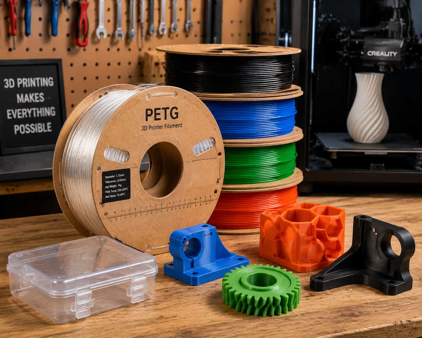
PETG strings. It strings more than PLA, more than ABS, and more than most other common filaments. The higher melt viscosity and stickiness that give PETG its excellent layer adhesion also make it reluctant to cleanly break away during retraction moves. Accepting a certain level of fine wisps — the “angel hair” that appears around PETG prints — is part of working with the material.
For Bowden extruders: 5-7mm retraction at 25-40mm/s. For direct drive: 1.5-3mm at 25-35mm/s. Increasing retraction speed beyond 40mm/s risks grinding the filament (PETG is softer than PLA at the extruder gear) without proportionally reducing stringing. If stringing persists at these settings, the filament is almost certainly wet — PETG is more hygroscopic than PLA (absorbing 0.3-0.5% moisture by weight) and wet PETG strings dramatically more than dry PETG. Dry at 60-65°C for 4-6 hours before printing.
Additional anti-stringing measures for PETG: enable “wipe on retract” (nozzle wipes 1-2mm after each retraction), enable “avoid crossing perimeters” (keeps travel moves inside the part), and enable “z-hop when retracting” at 0.2-0.4mm height (lifts the nozzle slightly to break strings). These settings together reduce stringing more effectively than any single aggressive retraction setting.
Moisture: PETG’s Silent Quality Killer
PETG absorbs moisture from ambient air more aggressively than the PETG filament datasheets typically acknowledge. At 50% relative humidity, PETG filament can absorb 0.3-0.5% moisture by weight within 48 hours. The effects of moisture on PETG printing are more subtle than the popping and spitting of wet nylon, but equally detrimental: increased stringing, hazy surface finish (especially noticeable on transparent PETG), reduced interlayer adhesion, and microscopic voids that reduce tensile strength by 10-20%.
The practical recommendation: dry new PETG filament at 60-65°C for 4-6 hours before first use, regardless of whether it arrived vacuum-sealed. Many manufacturers do not adequately dry filament before packaging, and the desiccant pack cannot remove moisture already absorbed by the filament. Store PETG in a sealed container with desiccant after drying, and re-dry after 1-2 weeks of exposure to ambient air. A filament dryer that feeds directly to the printer is ideal for PETG, as it eliminates the re-absorption window between drying and printing.
Annealing PETG: Worth It for Heat Resistance
PETG can be annealed to improve its heat deflection temperature and crystallinity — a capability that PLA does not share. Annealing involves heating the printed part to a specific temperature, holding it there for a set time, and cooling it slowly. For PETG, the annealing protocol is 60-80°C for 30-60 minutes, followed by slow cooling to room temperature over 1-2 hours (turning off the oven and leaving the part inside works well).
Annealing PETG increases its HDT from approximately 70°C to 80-85°C by allowing partial crystallization and stress relaxation. The tradeoff is dimensional change: PETG shrinks 0.2-0.5% in X and Y and 0.5-1.0% in Z during annealing as residual stresses from the printing process relax. For dimensionally critical parts, print test coupons, measure the shrinkage, and scale the print dimensions accordingly before annealing the final parts. Annealing also reduces transparency — annealed PETG parts become slightly hazy as small crystallites scatter light — so the process is best reserved for functional parts where heat resistance matters more than appearance.
Key Applications: Where PETG Excels
Printer Parts and Structural Components
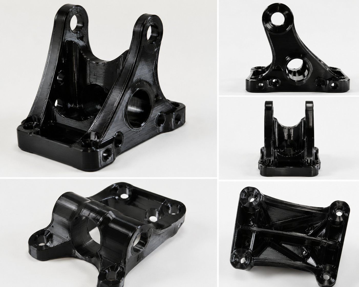
PETG is the standard material for 3D printer structural components — toolhead mounts, gantry parts, motor brackets, and enclosure panels. The Voron Design project, one of the most influential open-source 3D printer designs, specifies PETG for all printed components. The reasoning is sound: PETG’s combination of stiffness (2.0 GPa flexural modulus), temperature resistance (80°C Tg), and ease of printing make it the ideal material for parts that hold motors, guide belts, and maintain dimensional accuracy in a heated enclosure at 50-60°C. If those dimensions need to translate cleanly into mating parts, our 3Dプリントの公差ガイド is the next reference to review.
Food Contact and Medical Applications
PETG is one of the few FDM materials that is commonly available in food-safe grades. The base polymer — glycol-modified PET — is the same chemistry used in food and beverage packaging. The caveats for FDM are the same as for any material: the printed surface is porous and difficult to sanitize, the pigments and additives in colored PETG may not be food-safe, and the brass nozzle can introduce lead contamination. Transparent, natural (unpigmented) PETG printed through a stainless steel nozzle is the closest FDM printing comes to food-safe, but it should be considered food-contact-grade, not food-safe, without independent verification.
Chemical-Resistant Parts
PETG resists many common chemicals that attack PLA. It is resistant to weak acids, alkalis, oils, greases, and alcohols including isopropyl alcohol — which crazes and cracks PLA. This makes PETG the default choice for laboratory jigs and fixtures, chemical storage racks, and any printed part likely to contact cleaning solvents. PETG is not resistant to strong acids (concentrated sulfuric, nitric), strong bases (sodium hydroxide solution), or chlorinated solvents (dichloromethane, chloroform), but its chemical resistance profile covers the vast majority of workshop and laboratory exposures.
Outdoor and Moisture-Exposed Parts
PETG’s low water absorption (0.1-0.2% at saturation, compared to 2-8% for nylon) and good UV resistance (inferior to ASA but dramatically better than ABS or PLA) make it suitable for outdoor applications where ABS would degrade and PLA would soften. Garden irrigation fittings, outdoor sensor housings, pool equipment brackets, and marine accessories are common PETG applications. For continuous outdoor UV exposure, ASA remains the better choice, but PETG outperforms both PLA and ABS in this category.
Transparent and Optical Parts
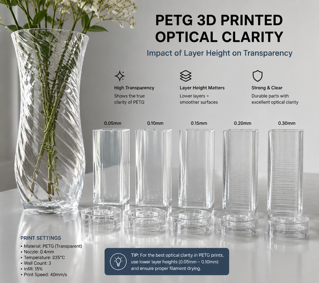
PETG can be printed with a high degree of transparency — a unique capability among common FDM materials. The key to transparent PETG prints is printing at the upper end of the temperature range (240-250°C) with minimal cooling (0-20% fan) and a large layer height (0.2-0.3mm for a 0.4mm nozzle) with 100% infill. These settings maximize interlayer fusion and minimize the air gaps and refractive index boundaries that create haze. Post-processing with a clear coat spray or epoxy further improves clarity by filling surface irregularities. For a broader look at clear-part strategy, see our transparent 3D printing guide.
PETG vs PLA vs ABS: The Decision Framework
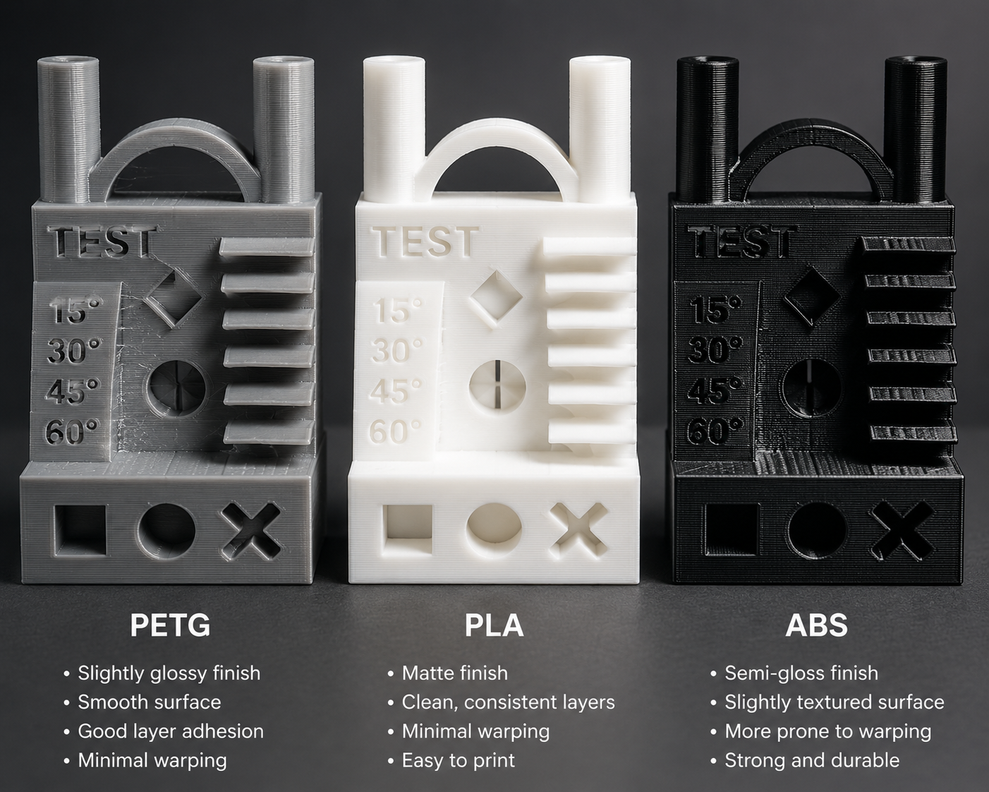
The choice between PETG, PLA, and ABS is the most common material selection decision in FDM printing, and the answer depends on a small set of application-specific questions:
| 基準 | Choose PLA If | Choose PETG If | Choose ABS If |
|---|---|---|---|
| 温度 | <50°C environment | 50-70°C environment | 70-95°C environment |
| Impact/Toughness | Low stress, display parts | Moderate impact, functional | High impact, snap-fit |
| 後処理 | Painting only | Limited (sanding difficult) | Full (sanding, vapor smoothing) |
| 化学物質への曝露 | Avoid solvents, IPA | Resists IPA, oils, weak acids | Similar to PETG |
| 印刷のしやすさ | Easiest, no enclosure | Easy+moderate, no enclosure | Difficult, needs enclosure |
| Transparency | Possible but limited | Best for transparent parts | Naturally opaque |
The decision flow that captures most cases: if transparency or chemical resistance is needed, choose PETG. If the part must survive 70-95°C or needs acetone vapor smoothing, choose ABS. For everything else — prototypes, display models, low-stress functional parts — choose PLA for its unmatched ease of printing, or PETG if impact resistance justifies the minor additional printing complexity.
Common PETG Printing Problems and Solutions
Nozzle Buildup: The Blob Problem
PETG accumulates on the nozzle more than any other common filament. The material’s stickiness combined with its tendency to curl slightly as it exits the nozzle means small amounts inevitably adhere to the nozzle surface. Over the course of a long print, this accumulation grows into a blob that eventually deposits on the print or falls off, creating a defect.
Solutions: use a silicone sock on the heater block (prevents PETG from sticking to the hot metal); reduce extrusion multiplier to 95-98% (slight underextrusion prevents the nozzle from dragging through excess material); increase Z-offset by 0.02-0.05mm (reduces nozzle contact with the print); and use a brass brush or nozzle wiper on the printer’s start G-code to clean the nozzle before each print. For long prints, periodic nozzle wiping during travel moves — enabled in the slicer as “wipe nozzle” — prevents accumulation from building to problematic levels.
Brittle PETG: The Wet Filament Trap
PETG that prints brittle — snapping easily rather than bending — is invariably wet. The moisture absorbed by the filament hydrolyzes the ester linkages in the PETG backbone during the heat of printing, reducing molecular weight and embrittling the material. A print that seems perfect off the bed can become brittle over days as residual moisture continues to hydrolyze the polymer. The solution is always drying: 60-65°C for 4-6 hours returns PETG to its as-manufactured mechanical properties. There is no slicer setting that compensates for wet filament.
Poor Overhangs and Bridging
PETG overhangs are challenging because the material stays soft for longer than PLA after extrusion — the lower cooling rate means the extruded bead can sag before solidifying. Solutions: increase part cooling to 50-60% for overhang regions specifically (most slicers support cooling overrides for bridges and overhangs); reduce print speed for overhangs to 50% of the normal perimeter speed; reduce layer height to 0.12-0.16mm for the overhang region (thinner layers cool faster and sag less); and consider using support material for overhangs greater than 45 degrees from vertical.
Conclusion: Why PETG Wins the Middle Ground
PETG is not the best at anything. PLA prints easier. ABS handles higher temperatures. PC is tougher. Nylon is more chemically resistant. ASA weathers better. But PETG is good enough at everything — printability, strength, temperature resistance, chemical resistance, clarity, cost — that it handles the majority of functional printing tasks without the specialized requirements that each of the “best” materials demands.
For the engineer who needs a bracket that survives a sunny window ledge, the hobbyist printing a replacement dishwasher part, the print farm operator who needs reliable output across dozens of printers, or anyone who has outgrown PLA but does not want to build an enclosure and deal with ABS fumes, PETG is the answer that works. It is not exciting. It is not exotic. It is just effective — and for most functional 3D printing, that is exactly what is needed.
よくある質問
なぜPETGがノズルに付着してしまうのでしょうか?
PETGのノズル詰まりは、この素材が本来持つ粘着性、わずかな過剰押出、およびノズルが以前に印刷された材料に接触することの組み合わせによって引き起こされます。 最も効果的な対策は、ヒーターブロックにシリコンソックスを取り付け、押出倍率を96~98%に下げ、Zオフセットを0.02~0.05mm増やして、ノズルがプリント面よりわずかに高い位置になるようにすることです。 また、印刷の開始時に真鍮製のブラシでノズルを拭くことも有効です。堆積が続く場合は、フィラメントが乾燥しているか確認してください。湿ったPETGは粘着性が高く、堆積しやすくなります。.
ガラスベッド上で、接着剤を使わずにPETGをプリントすることはできますか?
これは強くお勧めしません。PETGは素のガラスに強固に接着し、部品を取り外す際にガラス表面から欠けが生じるほどの強度でくっついてしまうことがあります。これは単なる理論上の懸念ではなく、実際に多くの事例が報告されている不具合です。印刷前に、ガラス表面にPVAスティックのりやヘアスプレーを薄く塗布し、剥離用の犠牲層としてください。 この接着剤は印刷後に水で溶解するため、安全にパーツを取り外すことができます。どうしても素のガラス上でPETGを印刷したい場合は、ベッドが室温まで完全に冷めるのを待ってから取り外しを試みてください。熱収縮の差によって接着が切れる可能性はありますが、ガラスが破損するリスクは依然として残ります。.
PETGのプリントを透明にするにはどうすればよいですか?
透明なPETGのプリントには、3つの条件が必要です。層間の融合を最大限に高めるための高いノズル温度(240~250°C)、 層間に空気の境界面が生じることなく融合する時間を確保するための最小限の部品冷却(0-20%ファン)、および層界面の数を減らすための大きな層高さ(0.4mmノズルの場合、0.2~0.3mm)です。 充填率は100%に設定し、単調なソリッド充填パターンで印刷してください。印刷されたパーツは完全に透明というよりは半透明になります。これは、層の境界線が依然として光を散乱させるためです。 透明アクリルスプレーや2液型エポキシコーティングによる後処理を行うと、表面の凹凸が埋められ、透明度が劇的に向上します。最良の結果を得るには、ノズルが対応する最大線幅(0.4mmノズルで0.6~0.8mmの押出幅)でプリントし、1層あたりの押出ライン数を最小限に抑えてください。.
PETGとPLA+:どちらが丈夫か?
PETGは標準的なPLAよりもはるかに靭性が高いですが、一部のPLA+(改質PLA)配合材と同等の靭性を示します。標準的なPLAのアイゾット衝撃強度は30~50 J/mですが、PETGは80~110 J/mの範囲にあり、高品質なPLA+では60~100 J/mに達することがあります。 しかし、破損様式は異なります。PLAおよびPLA+は、伸び限界(5~15%)に達すると脆性破断を起こしますが、PETGは破断する前に降伏して伸び(15~25%の伸び)を示します。 この延性のある破損様式により、PETG製の部品は粉砕することなく変形することで過負荷に耐えることができます。これは、予期せぬ荷重を受ける可能性のある機能部品にとって極めて重要な違いです。過負荷下での延性が極限強度よりも重要となる用途では、データシートの数値が類似していても、PETGの方がより安全な選択肢となります。.