Good 3D printing tolerances come from matching machine capability, material behavior, and fit design. FDM 3D printing offers incredible design freedom, but when it comes to precision — the ability to hold consistent tolerances — it struggles compared to traditional manufacturing methods like CNC machining or injection molding. For engineers designing functional parts that must fit, slide, snap, or seal, understanding what tolerances FDM can realistically achieve — and how to design for them — is essential.
This guide covers everything from root causes of dimensional error to printable tolerance tables, calibration workflows, and design strategies for press fits, sliding fits, and threaded assemblies. If thermal distortion is part of the problem too, our 3Dプリントの反り対策ガイド is a useful companion because flatness and fit errors often share the same root cause.
Why FDM Tolerances Matter for Functional Parts
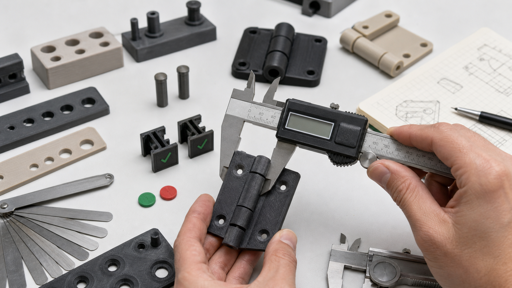
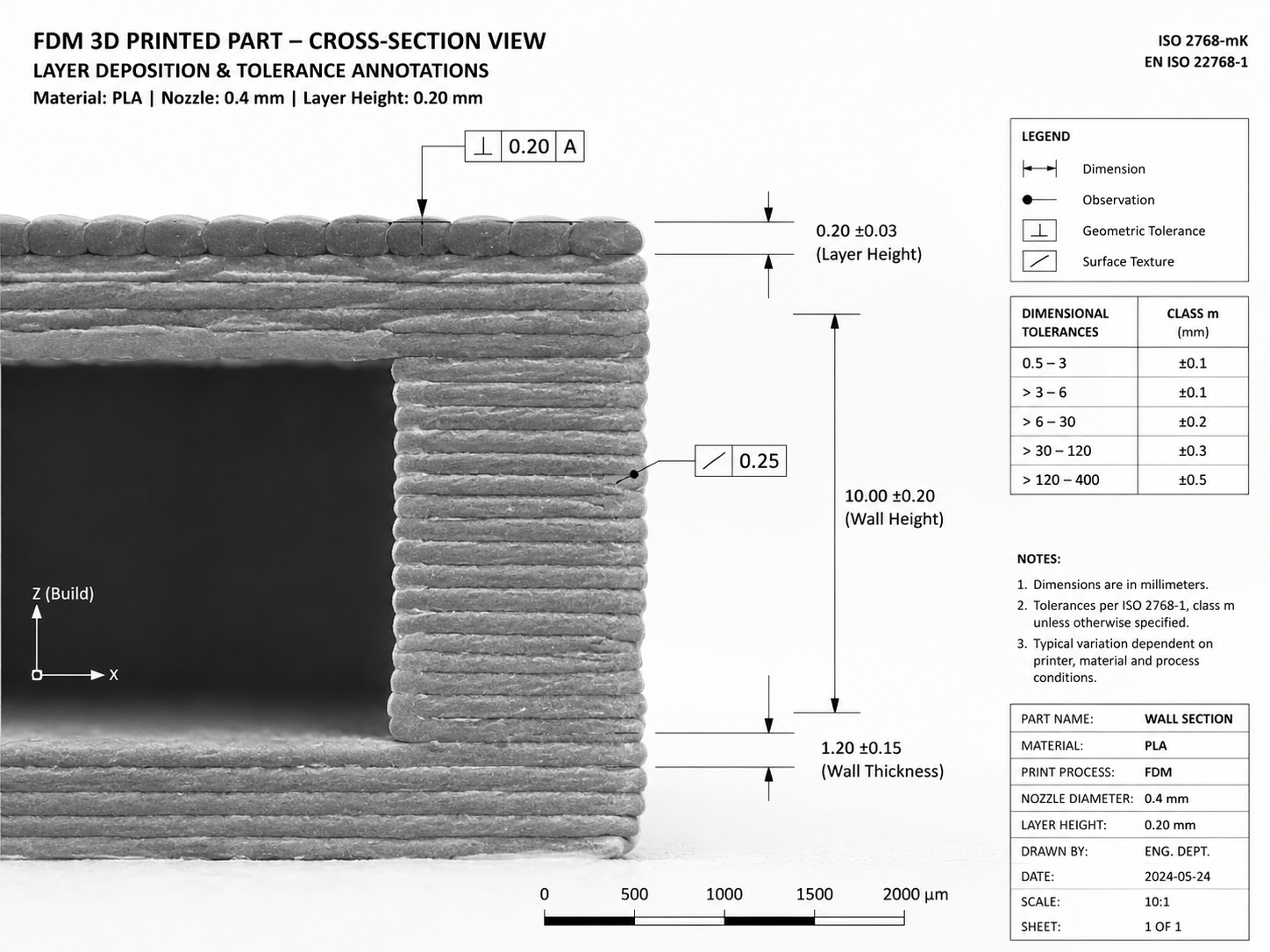
Unlike injection molding or CNC machining — where tolerances of ±0.05 mm are routine — FDM operates in a different regime. The combination of molten polymer extrusion, layer-by-layer deposition, and thermal contraction creates inherent dimensional variability. If you design a hole expecting ±0.1 mm but your printer delivers ±0.5 mm, your assembly will fail. Designing for FDM means understanding your printer’s actual capability and then applying fit strategies that account for its limitations.
Root Causes of Dimensional Error in FDM
| Error Source | Typical Contribution | 特徴 |
|---|---|---|
| Filament diameter variation | ±0.05 mm per wall | Systematic, consistent across layers |
| Thermal contraction (shrinkage) | 0.2% – 0.8% linear | Proportional to part size; material-dependent |
| Stepper motor quantization | ±0.0125 mm per mm | Deterministic; can be calibrated out |
| Mechanical backlash | ±0.05 – 0.2 mm | Direction-dependent; worse on worn machines |
| Z-axis lead screw irregularity | ±0.02 – 0.1 mm per 100 mm | Periodic; detectable in calibration cubes |
| Layer height quantization | ±0.5 × layer height | Vertical features only; affects hole roundness |
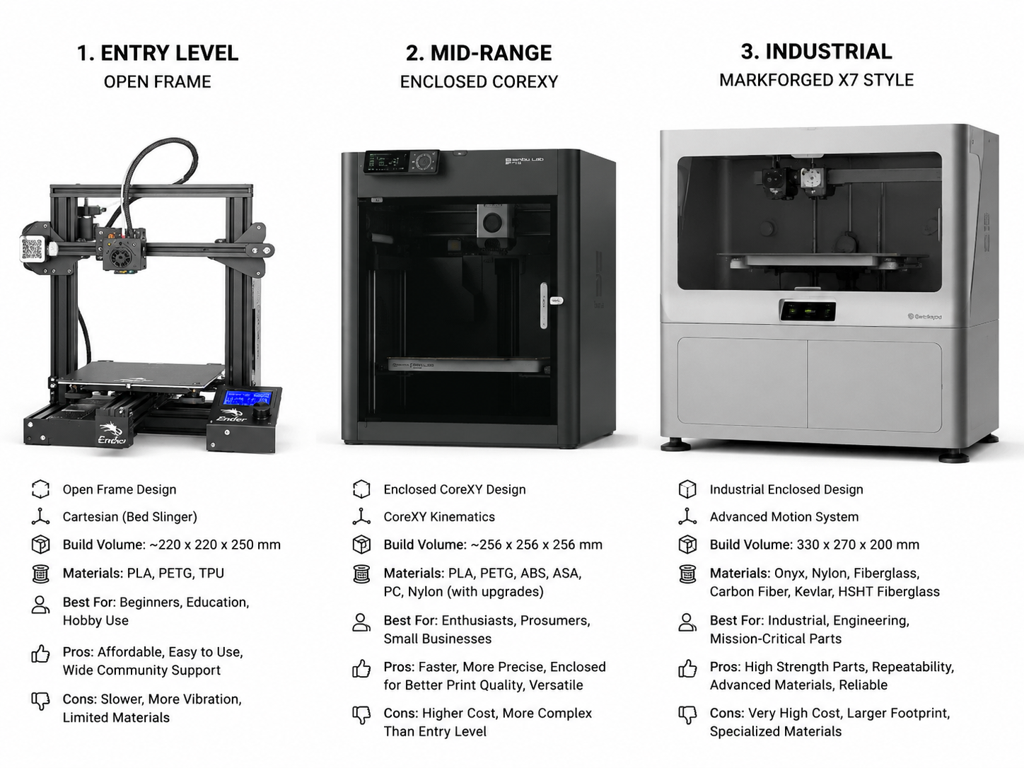
Realistic FDM Tolerance Capability by Printer Class
| Printer Class | XY Tolerance | Z Tolerance | Hole Accuracy | Min Feature |
|---|---|---|---|---|
| Entry-level (Ender 3, Anycubic) | ±0.2 – 0.5 mm | ±0.1 – 0.3 mm | ±0.3 – 0.5 mm | 0.8 mm |
| Mid-range (Bambu P1S, Prusa MK4) | ±0.08 – 0.2 mm | ±0.04 – 0.1 mm | ±0.1 – 0.25 mm | 0.4 mm |
| Industrial (Markforged X7) | ±0.05 – 0.13 mm | ±0.025 – 0.08 mm | ±0.05 – 0.1 mm | 0.2 mm |
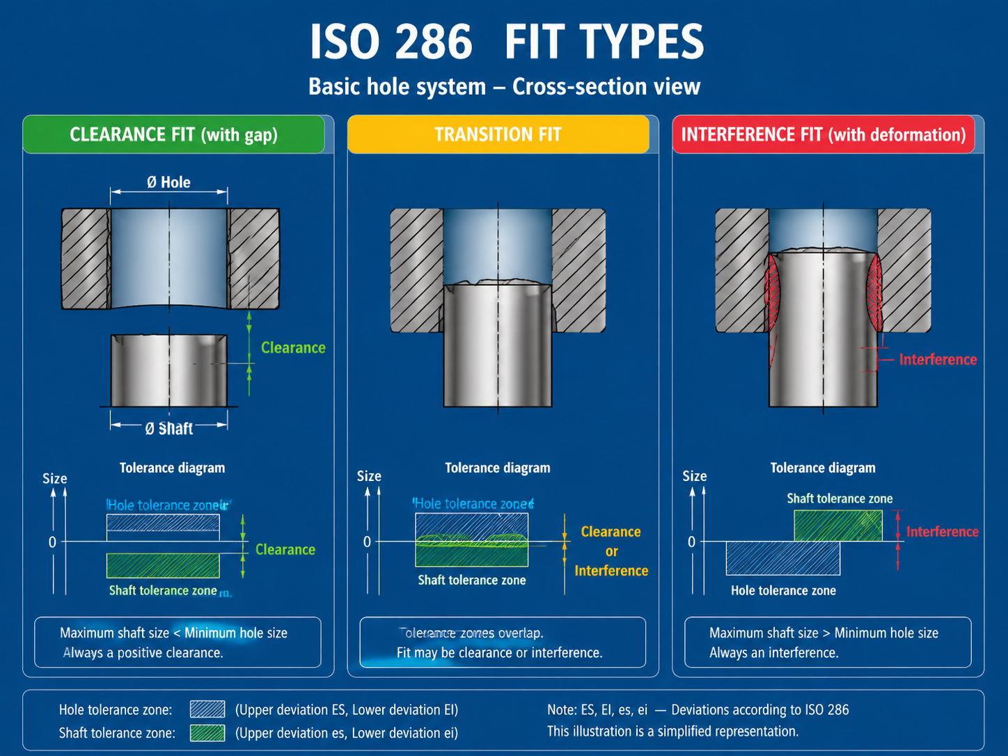
Designing for Fit: Clearance, Transition, and Interference
Clearance Fit
The shaft is smaller than the hole — parts move freely. For FDM, add 0.3 – 0.5 mm clearance per side for entry-level printers, 0.15 – 0.25 mm for mid-range machines. This ensures smooth sliding even with surface roughness from layer lines.
Transition Fit
The shaft and hole are close to the same size — parts may be loose or tight depending on actual dimensions. This is the most challenging fit for FDM because the tolerance band (±0.25 mm) often overlaps with printer capability. Plan for post-processing if this fit is critical.
Interference (Press) Fit
The shaft is larger than the hole — parts must be pressed together. For FDM, 0.1 – 0.2 mm interference per side works for mid-range printers with PLA, PETG, or Nylon. Over 0.3 mm per side risks cracking the hole wall. Use chamfers on both parts to aid assembly.
Recommended Fit Allowances for FDM
| Fit Type | Entry-Level | Mid-Range | インダストリアル | Example |
|---|---|---|---|---|
| Sliding / loose | +0.5 mm | +0.3 mm | +0.15 mm | Drawer slide, hinge pin |
| Snap / push | +0.2 mm | +0.1 mm | +0.05 mm | Cap closure, battery cover |
| Press fit | −0.15 mm | −0.1 mm | −0.05 mm | Bearing insert |
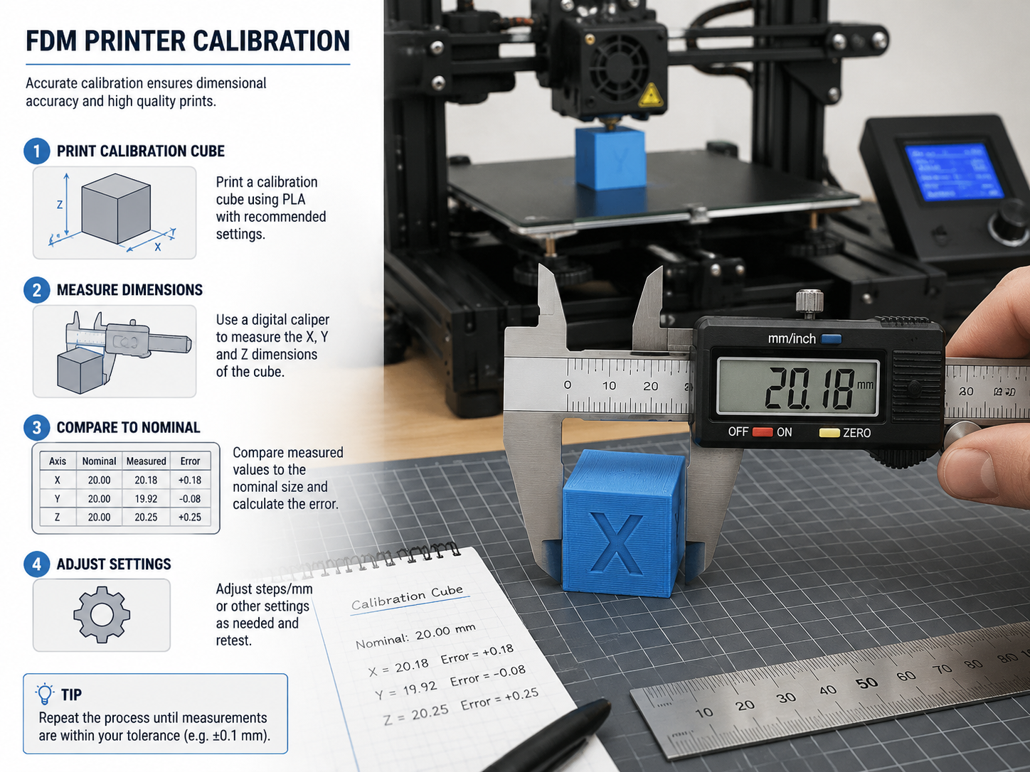
Calibration Workflow for Optimal Tolerances
Step 1: Extruder E-Steps — Mark 120 mm of filament above the extruder, extrude 100 mm, measure difference. Adjust rotation_distance = current × (100 / actual extruded).
Step 2: XY Steps Calibration — Print 20 mm calibration cube. Measure X, Y, Z with digital calipers. Adjust steps proportionally until all axes within 0.1 mm of nominal.
Step 3: Extrusion Multiplier — Print single-wall cube (1 perimeter, 0% infill, no top/bottom). Measure wall thickness with micrometer. Adjust extrusion multiplier = current × (nominal thickness / measured). Target: within ±0.05 mm.
Step 4: Linear / Pressure Advance — Print K-value calibration pattern. Select value where corners are sharp without bulging. PA errors cause 0.1–0.3 mm dimension errors at corners.
Step 5: Temperature Tower — Print for each new filament spool. Find sweet spot between layer adhesion and dimensional stability. Same-brand filaments from different batches can require ±10 °C adjustments.
Design Strategies for Better FDM Tolerances
Hole Compensation
FDM holes typically print 0.2 – 0.4 mm undersized due to nozzle geometry and material contraction. Apply horizontal expansion on hole walls: +0.15 mm per side for 0.4 mm nozzles, +0.25 mm for 0.6 mm nozzles. Or design holes 0.3 mm larger and test-fit before production.
Elephant’s Foot Compensation
The first few layers bulge outward by 0.1 – 0.3 mm. Use compensation in your slicer (−0.15 mm for first 3–5 layers). Design a 0.3 mm chamfer on bottom edges of mating features for precision assemblies.
Threaded Features
Design holes 0.3 mm larger than nominal for tapping, 0.5 mm larger for clearance. Use heat-set threaded inserts for repeated assembly — they are far more reliable than printed threads in FDM.
Post-Processing for Precision
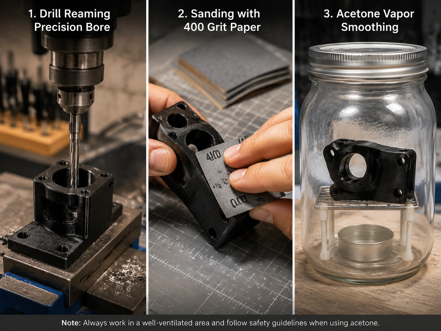
- Drill reaming — Use reamer or precision drill bit 0.1 mm under target, finish with exact size. Produces accurate holes regardless of printer XY error.
- Sanding shafts — Wrap 220 → 400 → 600 grit sandpaper around flat block. Remove 0.05 – 0.1 mm per pass while checking fit with go/no-go gauge.
- Acetone vapor smoothing — ABS only. Seal part above acetone pool in glass container for 3–10 minutes. Outer layer reflows for smooth surface. Parts shrink ~0.1 mm per side — account in design.
- CNC加工 — Print oversize and machine to ±0.025 mm. Combines FDM geometric freedom with CNC accuracy for industrial applications.
結論
- Know your printer’s actual tolerance — measure it, don’t guess
- Apply fit allowances: +0.3 to +0.5 mm sliding, −0.1 to −0.15 mm press fit
- Calibrate systematically: e-steps → XY → extrusion multiplier → pressure advance
- Compensate for holes, elephant’s foot, and threads in your design
- Plan post-processing when sub-0.1 mm accuracy is required
Buyer Problems Behind Tolerance Disputes
- A drawing applies one tight tolerance to every feature without identifying assembly function.
- The quote does not state FDM, SLS, MJF, SLA, orientation, support removal, or post-processing.
- Holes, pins, snaps, threads, and sliding fits are approved without representative coupons or mating parts.
- Inspection method, datum scheme, conditioning, and measurement temperature are undefined.
ナイロンプラスチックが本プロジェクトをどのように支えているか
Nylon Plastic has supported material selection and finished plastic-part manufacturing since 2005. The same project review can connect process selection, fit allowances, calibration parts, secondary machining, and assembly validation, so buyers do not have to evaluate each production decision in isolation.
- Review the drawing, material, quantity, critical features, and use environment before quotation.
- Compare 3D printing, CNC machining, rapid tooling, and production molding when more than one route is practical.
- Define samples, dimensional reports, material documents, traceability, and acceptance criteria before release.
関連記事
3D Printing Tolerances Depend on the Process and the Fit
There is no universal 3D printing tolerance that applies to FDM, SLA, SLS, MJF and DLS. Machine calibration, material shrinkage, orientation, feature size, layer or voxel behavior, support removal and post-processing all affect the finished fit. A useful tolerance recommendation starts with the mating parts and the assembly motion, then uses a small test coupon to confirm the actual machine and material combination.
Define whether the feature is a clearance hole, press fit, sliding fit, snap fit, thread, pin, slot or cosmetic surface. State the nominal size, load, insertion force, motion, temperature, conditioning and inspection method. A nominal CAD clearance is not the same as a measured clearance after printing, depowdering, curing, machining or coating.
| プロセス | Typical fit risk | What to validate |
|---|---|---|
| 多重伝送装置 | Layer direction, first-layer spread, corner shape and anisotropic shrinkage | Orientation, nozzle, layer height, wall count and hole coupon |
| エスエルエー | Cure growth, resin swelling, support marks and post-cure change | Wash, cure cycle, support position and measured feature size |
| SLS | Powder removal, thermal shrinkage, small-hole closure and surface texture | Build orientation, powder condition, hole/pin and clearance coupon |
| MJF | Thermal distortion, feature scale, powder removal and local shrinkage | Machine, material, orientation, wall thickness and batch condition |
| DLS | Layer and cure behavior, support removal and dimensional change | Material, cure, support strategy and post-process inspection |
Holes, Pins, Slots, Threads and Walls
Small holes often print undersize because of voxel size, bead shape, powder packing, resin cure or post-processing. A long horizontal hole may also change shape when orientation changes. Pins can become oversized because material accumulates at corners or because the printer’s compensation is not uniform. Slots and thin walls need their own coupon because a size that prints successfully in one orientation may close or warp in another.
Threads should be selected around the process and the number of assembly cycles. Printed threads may need a larger clearance, a coarse profile, a tapped post-process or a metal insert. For a snap fit, define strain, radius, orientation and repeated cycles rather than accepting a visual fit. The final allowance should be recorded in the drawing and tied to a verified machine, material and orientation.
| 特集 | Starting question | Recommended evidence |
|---|---|---|
| Clearance hole and pin | Must it slide, locate or rotate? | Pin-hole coupon at the actual nominal size |
| Press fit | What insertion force and material stress are acceptable? | Force measurement, section check and cycle test |
| Slot or latch | Does the feature need flex, clearance or a hard stop? | Assembly coupon and repeated-use test |
| Printed thread | How many cycles and what torque are required? | Thread gauge, torque test and post-process record |
| Thin wall | Will it survive print, cleaning and handling? | Wall-thickness coupon and dimensional inspection |
Orientation, Shrinkage and Post-Processing
Orientation affects layer strength, support contact, surface finish, heat flow and dimensional error. Choose orientation around the functional load and the critical features, not only the shortest build time. For powder processes, consider packing and thermal gradients. For resin processes, include wash and cure. For FDM, include first-layer behavior, cooling and the direction of the bead relative to the load.
Measure the printed part after the post-process state that will be used for assembly. If the part will be annealed, tumbled, coated, machined or conditioned, include that step before setting the final allowance. A supplier should report machine, material, orientation, build condition, post-process, sample quantity, datum and inspection method instead of publishing a universal guarantee.
Fit Coupons and Inspection Evidence
A practical coupon can include a series of pins and holes, slots, external and internal threads, thin walls, snap features and surface steps. Print it with the same orientation, material, layer or powder condition and post-process as the production part. Measure the features with the intended instrument and record the result by location. The coupon is most useful when it is tied to a clear acceptance decision: free movement, insertion force, leakage, torque or dimensional limit.
3D Printing Tolerance RFQ Checklist
- Process, machine, material, batch and intended orientation.
- CAD, datum, feature size, fit type, load and assembly cycles.
- Hole, pin, slot, thread, wall and clearance requirements.
- Post-processing, conditioning, coating and measurement state.
- Coupon design, sample quantity, instrument and acceptance limit.
- Prototype quantity, packaging, inspection report and production transition.
Send the process and material, CAD, fit type, feature size, quantity and inspection requirement. We can recommend a starting allowance, fit coupon and verification plan for the actual machine rather than relying on a generic printed-part tolerance.
よくある質問
What tolerance should be used for a 3D printed assembly?
There is no universal value. Process, machine, material, orientation, feature size, finish, and fit type determine the allowance. Validate representative coupons and the actual assembly.
Why do printed holes often come out undersized?
Layer approximation, extrusion width, shrinkage, powder or resin behavior, support effects, and calibration can all reduce holes. Critical bores may need design compensation or secondary drilling and reaming.
Can threads be printed directly?
Large coarse threads may work when the process and load allow it. Small, repeated, or torque-critical threads usually benefit from inserts, tapping, or machining.
How should critical printed dimensions be inspected?
Define datums, orientation, conditioning, post-processing state, measurement equipment, sample size, and mating-part checks before production.
Request a 3D Printing Tolerance Review
Send the CAD, drawing, process preference, material, quantity, mating parts, and critical dimensions for a fit and inspection review.