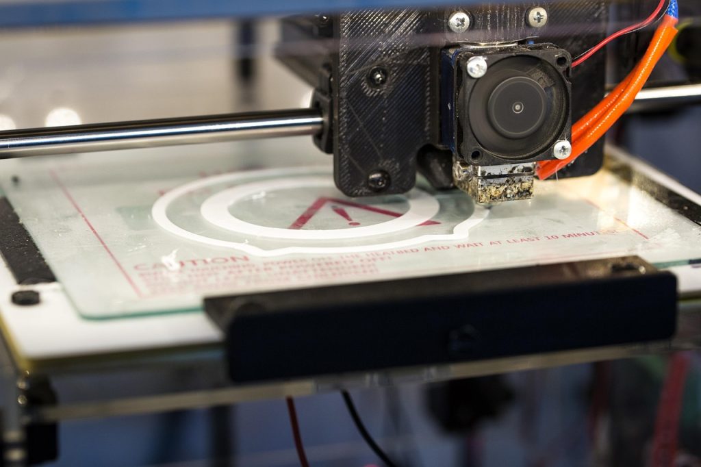
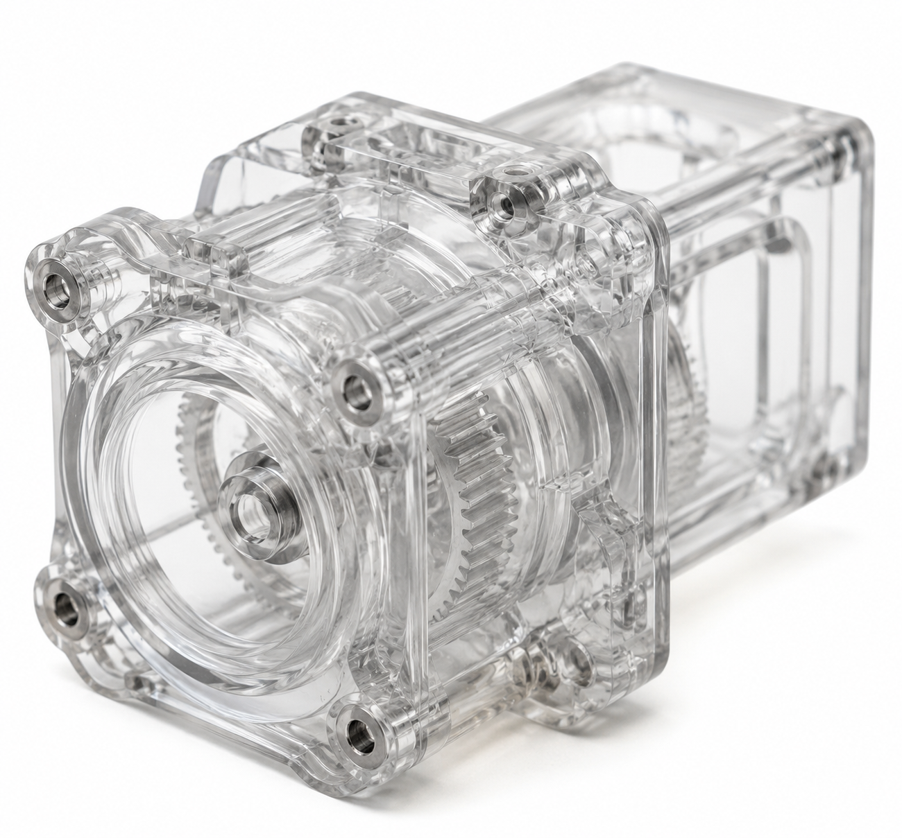
Transparent 3D printing represents one of the most sought-after capabilities in additive manufacturing for functional prototyping. Whether you are an engineer validating fluid flow paths, a product designer creating see-through enclosures, or a manufacturer proving a concept before tooling investment, printing optically clear parts on an FDM machine is both achievable and cost-effective when you understand the underlying physics.
This guide breaks down every variable that affects transparency in FDM printing — from material selection and print temperature to layer bonding chemistry and post-processing workflows — so you can consistently produce parts that meet your clarity requirements.
Why Transparent 3D Printing Matters for Engineering and Prototyping
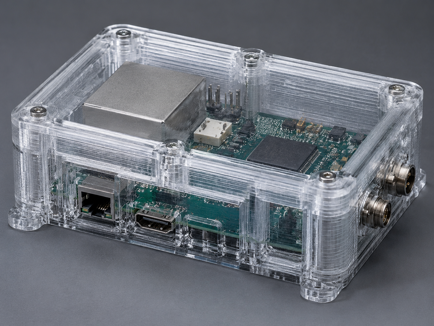
The ability to see through a printed part transforms its utility across multiple stages of product development. In fluid dynamics testing, transparent prototypes let you visualize flow patterns, identify dead zones, and validate channel geometries without expensive CNC machining of acrylic blocks. For electronic enclosure development, clear housings enable visual inspection of component placement, thermal imaging of hotspots, and ergonomic assessment of internal routing.
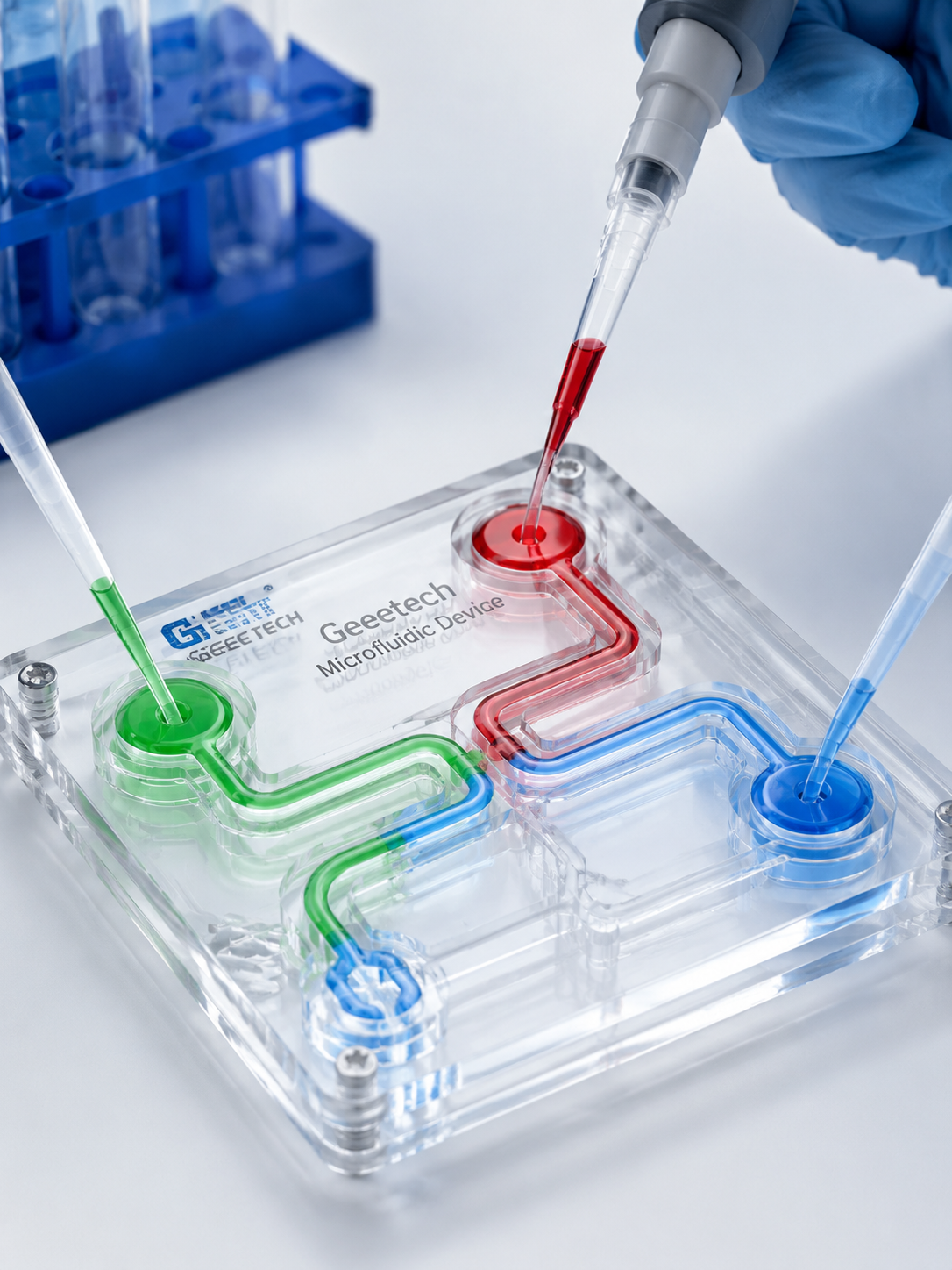
Medical device prototyping benefits particularly from transparent printing: microfluidic chips, surgical guides with internal channel verification, and anatomical models with embedded features all require material transparency that injection molding would only achieve after significant tooling investment. The economics are compelling — a transparent FDM prototype costs 5-15% of what a single-cavity clear injection mold would, and turnaround drops from 4-6 weeks to overnight.
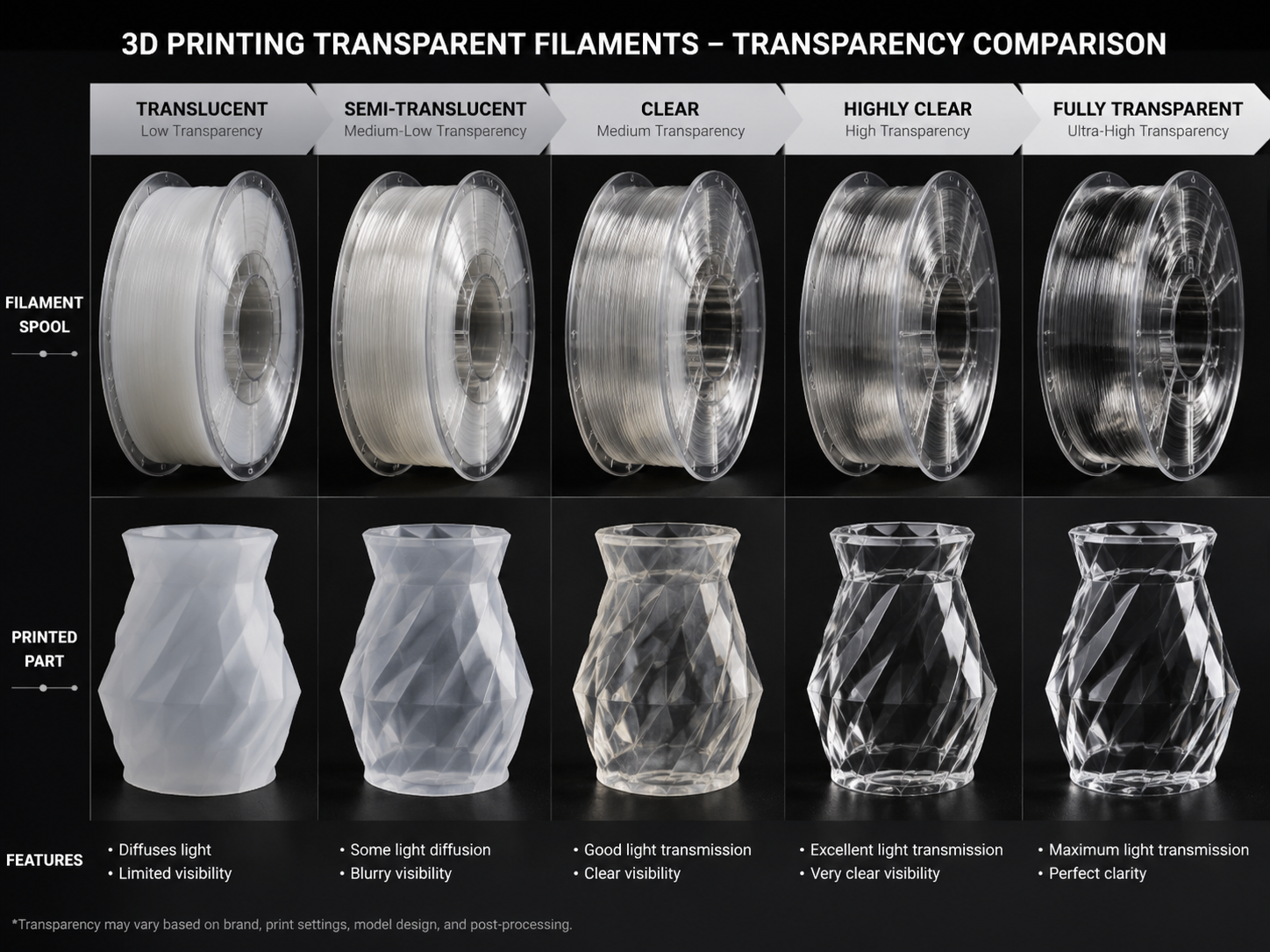
Beyond prototyping, transparent 3D printing finds production applications in custom optical diffusers, light pipe prototypes for automotive lighting, LED lens development, and low-volume transparent covers where tooling amortization does not justify injection molding. The key is understanding that FDM transparency is not a binary property but a spectrum, and your application requirements dictate where on that spectrum you need to land.
Best Materials for Transparent 3D Printing: A Comprehensive Comparison
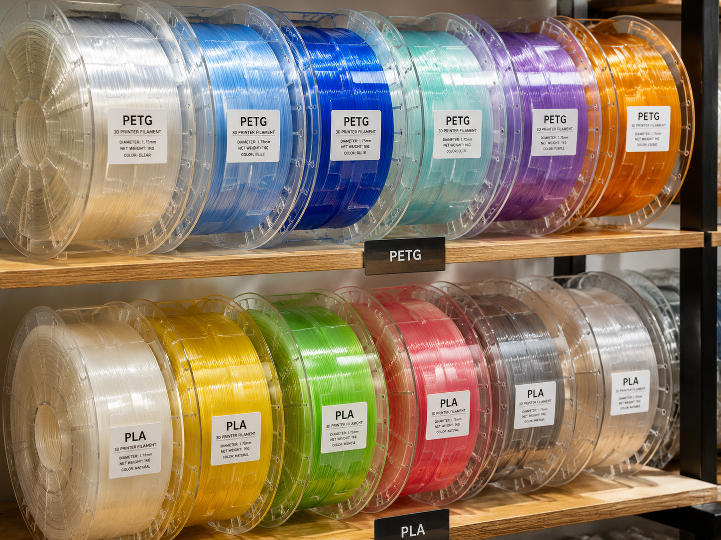
Not all clear filaments are created equal. Each material brings a different balance of optical clarity, mechanical properties, print difficulty, and cost. Selecting the right one requires matching your application requirements against what each material can deliver.
Transparent PLA
Polylactic acid in its natural, uncolored form is inherently translucent. Natural PLA has light transmission around 85-90% in thin sections, placing it between translucent and transparent. It is the most accessible starting point for clear printing — prints at low temperatures (190-210°C), requires no heated enclosure, and costs $20-30/kg. However, PLA’s glass transition temperature of roughly 60°C limits its use in any application exposed to heat, and its mechanical properties are modest (tensile strength approximately 50 MPa, low impact resistance).
For applications like visual mockups, concept models, low-temperature fluidic demonstrations, and educational visual aids, transparent PLA offers the easiest path to acceptable clarity. Post-processing with acrylic spray coating can push its clarity from translucent to nearly transparent.
Transparent PETG
PETG in its natural, uncolored state is the workhorse of transparent FDM printing. It provides better clarity than PLA straight off the print bed — typically 88-92% light transmission in 2mm sections — with significantly better mechanical properties: tensile strength around 50-55 MPa, impact resistance several times that of PLA, and a glass transition near 80°C. This makes transparent PETG suitable for functional prototypes that need to survive handling, assembly, and moderate thermal exposure. For the broader process workflow, see our PETGプリントガイド.
PETG prints at 230-250°C and benefits from a heated bed at 70-80°C. It is more hygroscopic than PLA, meaning proper drying before printing (65°C for 4-6 hours) is essential to prevent bubbles and haze in transparent parts. PETG is also prone to stringing, which matters for transparency because fine strings between surfaces scatter light. Dialing in retraction settings — typically 4-6mm at 30-40mm/s — is critical for clear PETG parts.
Common transparent PETG applications include electronic enclosures, fluidic test fixtures, medical device housings, and any prototype where clarity plus durability is required. At $25-40/kg, the cost premium over PLA is modest given the performance gain.
Transparent PC (Polycarbonate)
Polycarbonate is the highest-performing transparent FDM filament, offering true optical clarity approaching 90% light transmission, outstanding impact resistance, and a glass transition at roughly 147°C. These properties make transparent PC the material of choice for demanding applications: automotive lighting prototypes, high-temperature fluidic devices, structural transparent parts, and anything requiring both clarity and mechanical integrity. Our PCフィラメントガイド goes deeper on drying, enclosure control, and process windows.
The tradeoff is printability. PC requires nozzle temperatures of 260-300°C, a heated bed at 90-110°C, and ideally a fully enclosed printer with ambient chamber heating to 50-70°C to prevent warping and layer delamination. All-metal hotends are mandatory — PTFE-lined hotends degrade above 240°C. PC is extremely hygroscopic; drying at 80°C for 8-12 hours before printing is essential, and printing directly from a dry box is recommended.
At $40-70/kg for quality transparent PC filament, this is the premium option. But for applications that genuinely need polycarbonate-level performance and clarity, there is no substitute in the FDM world.
Transparent PMMA (Acrylic)
PMMA filament aims to replicate the optical clarity of cast acrylic sheet in FDM form. In theory, PMMA offers the highest potential transparency among all FDM materials — up to 92% light transmission. In practice, achieving this requires near-perfect print settings and aggressive post-processing. PMMA prints at 240-260°C, requires a heated bed at 100-110°C, and is extremely brittle compared to PC or PETG.
The brittleness is the main practical limitation: PMMA filaments often snap during handling, and removing supports from PMMA prints frequently causes cracking. Post-processing with solvent vapor (acetone or dedicated PMMA solvents) can dramatically improve clarity but requires careful technique to avoid surface frosting. PMMA is a specialty material for specific optical applications; for general transparent prototyping, PETG or PC are more practical choices.
Material Selection Quick Reference
| プロパティ | Natural PLA | PETG | PC | PMMA |
|---|---|---|---|---|
| 光透過率 | 85-90% | 88-92% | 88-90% | 90-92% |
| Nozzle Temp | 190-210°C | 230~250°C | 260-300°C | 240~260°C |
| Bed Temp | 50~60°C | 70-80°C | 90~110°C | 100-110°C |
| Enclosure Needed | いいえ | おすすめ | 必須 | 必須 |
| 耐衝撃性 | 低い | 高い | 非常に高い | Low (Brittle) |
| コスト/kg | $20-30 | $25-40 | $40-70 | $35-60 |
| 最適 | Visual mockups, low-temp demos | 機能試作機、筐体 | High-temp structural, automotive | Optical prototypes, light pipes |
How to Achieve Maximum Transparency: Print Settings and Techniques
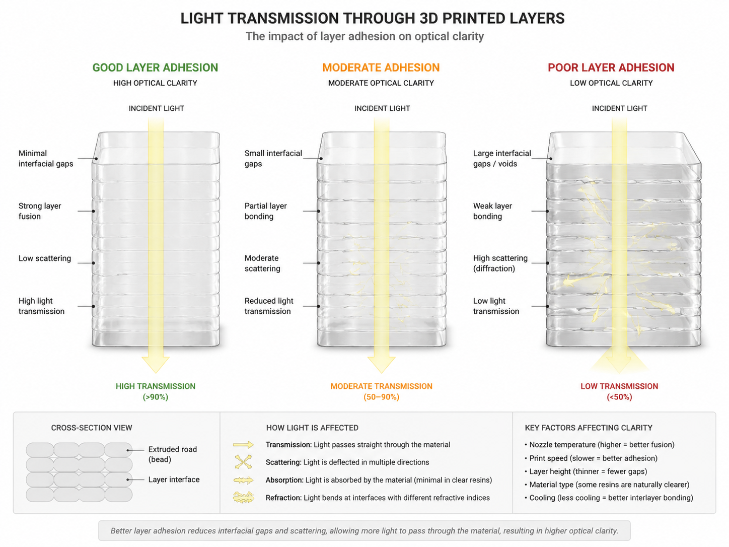
The difference between a cloudy, opaque-looking print and one you can read text through is almost entirely in the print settings. Transparency in FDM is fundamentally about minimizing light scattering at layer interfaces, which means maximizing interlayer polymer chain entanglement and eliminating air gaps.
Nozzle Temperature: The Single Most Important Variable
Higher nozzle temperatures improve transparency dramatically by reducing melt viscosity, which allows the extruded filament to flow more completely into the previous layer. This better wetting and penetration creates stronger polymer chain entanglement across layer boundaries, minimizing the refractive index discontinuity that causes scattering. For transparent PLA, printing at 215-225°C (15-25°C above normal) typically yields the best clarity. For PETG, 250-260°C. For PC, 290-300°C.
A practical test: print a small 20x20mm square at 5°C temperature increments starting from normal printing temperature up to the filament maximum. Hold each square up to a printed page of text. The temperature at which you can just start reading text through the part is your clarity threshold. Going higher usually improves further until you reach the point where thermal degradation begins (visible as yellowing or surface roughness).
Layer Height and Extrusion Width
Counterintuitively, larger layer heights often produce better transparency than smaller ones. At 0.1mm layer height, you have many more interfaces per millimeter of part thickness, creating more scattering surfaces. At 0.2-0.3mm, fewer interfaces mean fewer scattering events, and the thicker extruded bead has more thermal mass to remelt the previous layer surface. The optimal transparent layer height varies by material but is typically 0.2-0.3mm for 0.4mm nozzles.
Extrusion width also matters. A wider extrusion width (0.5-0.6mm on a 0.4mm nozzle, or better yet a 0.6-0.8mm nozzle) creates a flatter, wider bead that increases the contact area with adjacent layers. Combine this with 100% infill — any infill pattern creates internal interfaces that scatter light — and you have the foundation for transparent printing.
印刷速度と冷却
Transparent printing demands slow speeds. At 30-40mm/s, the extruded filament stays molten longer, giving it more time to fuse with the previous layer. Printing faster than 50mm/s typically produces visible haze regardless of temperature, because the polymer cools below its glass transition before achieving full interlayer diffusion. For PC, speeds as low as 20-30mm/s may be necessary.
Cooling fan strategy is equally important. Active part cooling should be minimal or off for the first several layers and then run at 20-50% for the remainder. Too much cooling freezes the extruded bead before it can bond properly; too little causes sagging and dimensional issues. For enclosed printers, maintaining a stable chamber temperature of 40-60°C (for PLA/PETG) or 70°C and above (for PC) slows cooling enough to significantly improve interlayer bonding and clarity.
Flow Rate and Extrusion Multiplier
Slightly over-extruding — typically 102-105% flow — helps transparency by ensuring there is no shortage of material to fill gaps between layers. Under-extrusion leaves microscopic voids at layer boundaries that act as powerful light scattering centers. However, over-extrusion beyond 110% creates dimensional inaccuracy and surface artifacts that hurt clarity through a different mechanism. The sweet spot for each filament needs experimental determination: print a small solid cube at flow rates from 98% to 108% and inspect the clarity progression.
Post-Processing for Optical Clarity
Print settings alone rarely achieve full transparency. Post-processing bridges the gap between “translucent” and “optically clear” by smoothing surface roughness and filling microscopic voids.
Mechanical Finishing
Wet sanding is the foundation of transparent post-processing. Start with 400 grit wet/dry sandpaper and progress through 600, 800, 1000, 1500, and 2000 grit, always sanding wet to prevent heat buildup that can haze the surface. Sand in alternating directions between grits to remove previous scratch patterns. After 2000 grit, the surface should appear uniformly frosted — this is a good sign, as it means the layer lines have been eliminated and only fine scratches remain.
Chemical Smoothing and Coating
The final clarity leap comes from chemical treatment. For PLA, a high-quality clear acrylic spray coating (such as Krylon or Rust-Oleum Crystal Clear) fills the microscopic scratches left by sanding, creating a smooth optical surface. Apply 3-5 thin coats with 10-15 minutes between each, then allow 24 hours for full cure. The result can achieve transparency where you can read 8-point text through a 3mm thick printed part.
For PETG, dichloromethane (DCM) vapor smoothing is the most effective chemical treatment but requires stringent safety precautions — fume hood, chemical-resistant gloves, and proper ventilation are mandatory. The vapor melts the outermost polymer layer, allowing it to flow and fill surface imperfections, then re-solidify as a smooth optical surface. Exposure times are typically 30-90 seconds, and the part must cure for 24 hours before handling.
For PC, a combination of mechanical polishing followed by a clear urethane coating typically produces the best results. Pure PC polishing compounds followed by a UV-resistant clear coat protect the part from both mechanical wear and UV yellowing over time.
Resin Coating Alternatives
An increasingly popular technique borrowed from the cosplay community involves brushing or dipping the sanded FDM part in UV-curable clear resin, then curing under UV light. This fills surface imperfections with an optically clear material that bonds well to the underlying plastic. The process is faster than multiple spray coats and can achieve comparable or better clarity, but requires careful control of resin thickness to avoid runs and drips.
Common Challenges and Troubleshooting
Why Is My Transparent Print Cloudy or White?
Cloudiness in transparent prints has four primary causes, each with a specific fix:
フィラメント中の水分 is the most common culprit. Hygroscopic filaments like PETG, PC, and nylon absorb moisture that vaporizes in the hotend, creating micro-bubbles in the extruded bead. These bubbles scatter light, producing a white or cloudy appearance. Always dry filament before printing — 4-6 hours at 65°C for PETG, 8-12 hours at 80°C for PC — and print from a dry box if possible. The storage discipline is very similar to what we cover in our ナイロンの乾燥方法.
Insufficient nozzle temperature is the second most common cause. If the extruded polymer is not hot enough to melt the surface of the previous layer, the boundary between layers acts as a partial mirror, reflecting and scattering light. Increase nozzle temperature in 5°C increments until clarity improves.
Too much cooling or too fast printing prevents the extruded bead from staying molten long enough to fuse with adjacent material. Reduce print speed to 30mm/s or below and minimize part cooling fan speed.
Under-extrusion leaves microscopic voids at layer interfaces. Increase flow rate by 2-3% and verify with a calibration cube.
Yellowing and Discoloration
Yellowing during transparent printing usually indicates thermal degradation — the polymer is being heated beyond its stable range. Reduce nozzle temperature by 5-10°C. If yellowing persists at recommended temperatures, the filament itself may have been overheated during manufacturing; try a different brand or batch. For PC specifically, some yellowing is inherent to the material and cannot be fully eliminated.
Visible Layer Lines Despite Post-Processing
If layer lines persist after sanding through 2000 grit, the most likely cause is insufficient sanding at the coarser grits. The 400-grit stage must completely remove all layer line texture before progressing. A common mistake is moving to finer grits too quickly. Check after 400-grit by running a fingernail across the surface — if you can feel any texture, continue at 400 grit until it is perfectly smooth.
業界を横断した活用事例
Transparent 3D printing has moved beyond the prototyping lab into production-adjacent and low-volume production applications across multiple industries:
Medical and Life Sciences: Microfluidic chips for diagnostic testing, surgical planning models with internal anatomical features, custom labware with integrated fluid channels, and transparent dental aligner models all benefit from clear 3D printing capabilities. The ability to iterate a microfluidic design overnight versus waiting weeks for PDMS casting represents a significant acceleration in R&D timelines.
自動車 Transparent PC printing enables functional testing of lighting components — LED light pipes, lens prototypes, and interior ambient lighting diffusers — before committing to injection mold tooling. The combination of PC’s high-temperature resistance and optical clarity makes it uniquely suited to under-hood and exterior lighting validation.
家電製品: Transparent enclosures for proof-of-concept devices, wearable prototypes requiring see-through housings, and IoT device mockups where internal component visualization accelerates design reviews and investor demonstrations.
産業用機器: Sight glasses for fluid systems, transparent covers for machinery inspection ports, and flow visualization chambers for process equipment. These are typically low-volume applications where injection molding costs cannot be justified, making FDM the economical production method.
Education and Research: Transparent demonstration models for engineering education — gear trains, pump mechanisms, valve assemblies — where students can observe internal operation in real time. The educational value of seeing mechanisms operate through transparent housings is difficult to overstate.
Summary: Key Principles for Transparent 3D Printing Success
Transparent FDM printing is a systematic process, not a guessing game. The most reliable path to optical clarity follows these principles in order of importance:
First, choose the right material for your application’s thermal, mechanical, and optical requirements — PETG for general functional prototypes, PC for high-performance applications, PLA for basic visual models.
Second, print hot and slow. Higher nozzle temperatures improve interlayer polymer diffusion, and slower print speeds give that diffusion time to occur. These two variables alone account for the majority of clarity improvement possible through print settings.
Third, eliminate moisture. Dry filament is non-negotiable for transparent printing. If you see any steam, popping sounds, or bubbles during extrusion, stop and dry the filament before continuing.
Fourth, use 100% infill with wide extrusion widths. Any internal structure creates light-scattering interfaces. Solid prints with maximum bead contact area minimize these interfaces.
Fifth, finish with progressive sanding and a clear coating. Even the best-printed part benefits from post-processing that fills surface-level imperfections and creates a smooth optical boundary.
With these principles applied systematically, transparent FDM printing moves from a frustrating exercise in trial-and-error to a reliable engineering process that delivers functional, optically clear parts suitable for professional prototyping and low-volume production.
よくある質問
Can you 3D print truly transparent parts with FDM?
Yes, but with nuance. FDM cannot achieve the optical clarity of injection-molded polycarbonate or cast acrylic without post-processing. However, with optimal print settings (high temperature, slow speed, 100% infill, dry filament) and post-processing (progressive wet sanding plus clear coating), FDM parts can achieve transparency sufficient for reading text through 3-5mm of material. The result is “functional transparency” — clear enough for fluid visualization, internal inspection, and light transmission — rather than “optical transparency” suitable for lenses or precision optics.
Which clear filament is easiest for beginners?
Natural/transparent PLA is the most beginner-friendly option. It prints at low temperatures (190-210°C), requires no enclosure, and is cheap enough ($20-30/kg) that experimenting with settings is low-risk. Start with PLA to learn the relationship between temperature, speed, and clarity, then progress to PETG for functional parts. Avoid PC and PMMA until you have mastered the fundamentals — their high temperature requirements and warping tendencies add significant complexity.
Why does my PETG transparent print have tiny bubbles?
Bubbles in transparent PETG prints are almost always moisture-related. PETG is hygroscopic — it absorbs water from ambient air. When this moisture enters the 230-250°C hotend, it flash-vaporizes into steam, creating pockets of gas trapped in the extruded bead. These pockets scatter light, appearing as white specks or overall cloudiness. Dry your PETG at 65°C for 4-6 hours before printing, and consider printing from a sealed dry box if your ambient humidity exceeds 50%.
Is polycarbonate (PC) worth the difficulty for transparent parts?
It depends on your application. If you need a transparent part that must survive temperatures above 100°C, withstand impact, or carry structural loads, then PC is the only FDM material that can deliver all three. The price is significant complexity: 260-300°C nozzle, 90-110°C bed, mandatory enclosure, aggressive drying, and slow print speeds (20-30mm/s). For most prototyping applications, PETG delivers sufficient clarity and mechanical performance at a fraction of the difficulty. Reserve PC for applications where PETG’s 80°C glass transition or impact resistance is genuinely insufficient.