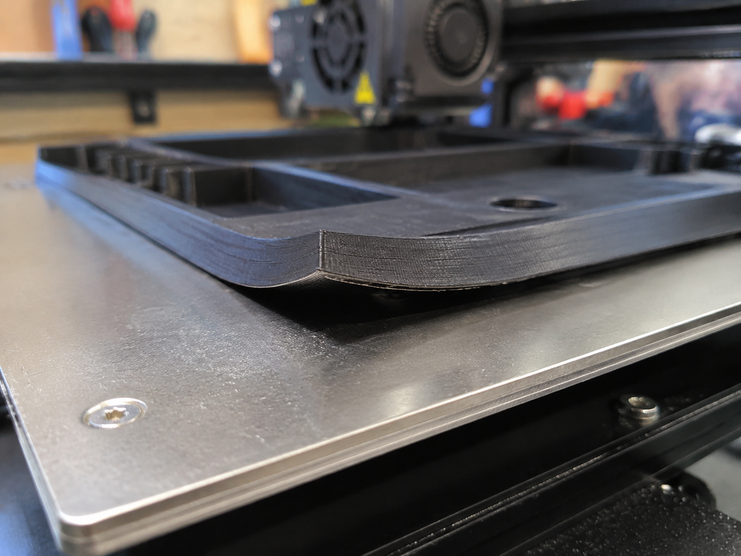
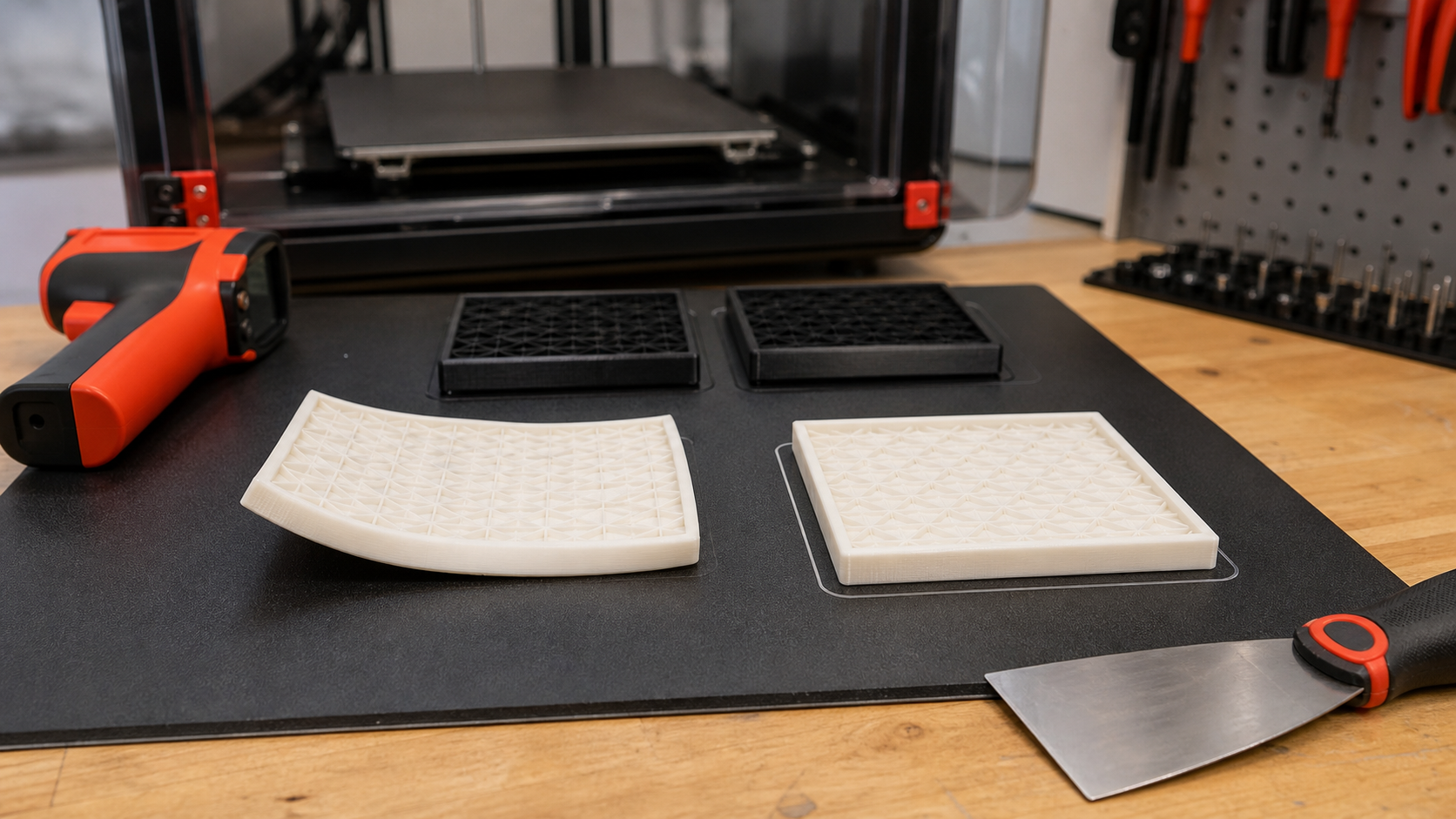
A reliable 3D print warping fix starts by separating shrinkage, adhesion, and enclosure problems. Warping is the number one print-killer in FDM 3D printing. You spend hours setting up a job, walk away, and come back to find corners lifted off the bed, layer shifts, or — worst case — a part that popped completely loose mid-print. For engineers and manufacturers using FDM for functional prototypes or end-use parts, warping isn’t just cosmetic: it destroys dimensional accuracy and can render a part unusable.
This guide explains the physics of warping, ranks materials by warp risk, and provides a systematic troubleshooting workflow — from bed preparation and print settings to enclosure design and advanced material substitution strategies. If nylon is one of the problem materials in your workflow, our ナイロンフィラメントの乾燥ガイド is a practical companion because moisture and thermal stress often show up together.
Why FDM Prints Warp: The Physics
Warping is driven by thermal contraction. When extruded filament leaves the nozzle at 200–300°C and cools to ambient temperature (20–40°C), it shrinks. The problem is that cooling isn’t uniform: the bottom layers in contact with the heated bed cool more slowly than upper layers exposed to ambient air. This creates a thermal gradient — and with it, internal stress. When that stress overcomes bed adhesion, the corners lift. The same shrinkage is also one reason FDM parts miss target fit, which we break down in our 3Dプリントの公差ガイド.
| ファクター | メカニズム | Effect on Warping |
|---|---|---|
| Coefficient of thermal expansion (CTE) | Material shrinks as it cools from extrusion temperature to ambient | High CTE materials (ABS, Nylon, PC) warp aggressively; low CTE (PLA, PETG) are forgiving |
| Differential cooling rate | Upper layers cool faster than bed-adjacent layers | Primary driver — creates bending moment at corners |
| Bed adhesion failure | Part separates from build surface when internal stress > adhesion force | Trigger event — stress accumulates until bond breaks |
| Crystallization shrinkage (semi-crystalline polymers) | Nylon, PEEK, PP undergo phase-change volume reduction | Adds 1–3% additional shrinkage beyond thermal contraction |
| Ambient air currents / drafts | Uneven cooling creates localized stress concentrations | Amplifies differential cooling; enclosure eliminates |
| Part geometry (sharp corners, large footprint) | Stress concentrates at corners; large flat areas accumulate more shrinkage | Largest parts with sharp corners warp worst |
Material Warping Risk: Ranked
| 素材 | Warp Risk | Bed Temp | Enclosure Required? | Best Bed Surface |
|---|---|---|---|---|
| PLA | 非常に低い | 50–60°C | いいえ | PEI smooth, textured PEI, blue tape |
| PETG | 低い | 70~85°C | No (enclosure helps consistency) | Textured PEI, glue stick on smooth PEI (release agent) |
| TPU | Low–Moderate | 40–60°C | いいえ | PEI smooth, glue stick |
| ABS | 高い | 95~110°C | Yes — mandatory | PEI smooth + enclosure heated to 45°C+ |
| ASA | 高い | 95~110°C | Yes — mandatory | PEI smooth + enclosure |
| Nylon (PA6, PA12) | 非常に高い | 80~100°C | Yes — heated enclosure strongly recommended | Garolite (G10), PVA glue stick, Magigoo PA |
| ポリカーボネート(PC) | 非常に高い | 110–130°C | Yes — heated enclosure essential | PEI smooth + glue stick, BuildTak, Magigoo PC |
| PP | Extreme | 85–100°C | Enclosure helps | PP-specific tape, PP sheet on bed |
| PEEK / PEI (Ultem) | Extreme | 130–160°C | Heated chamber 80–120°C mandatory | PEI sheet, specialty high-temp adhesives |
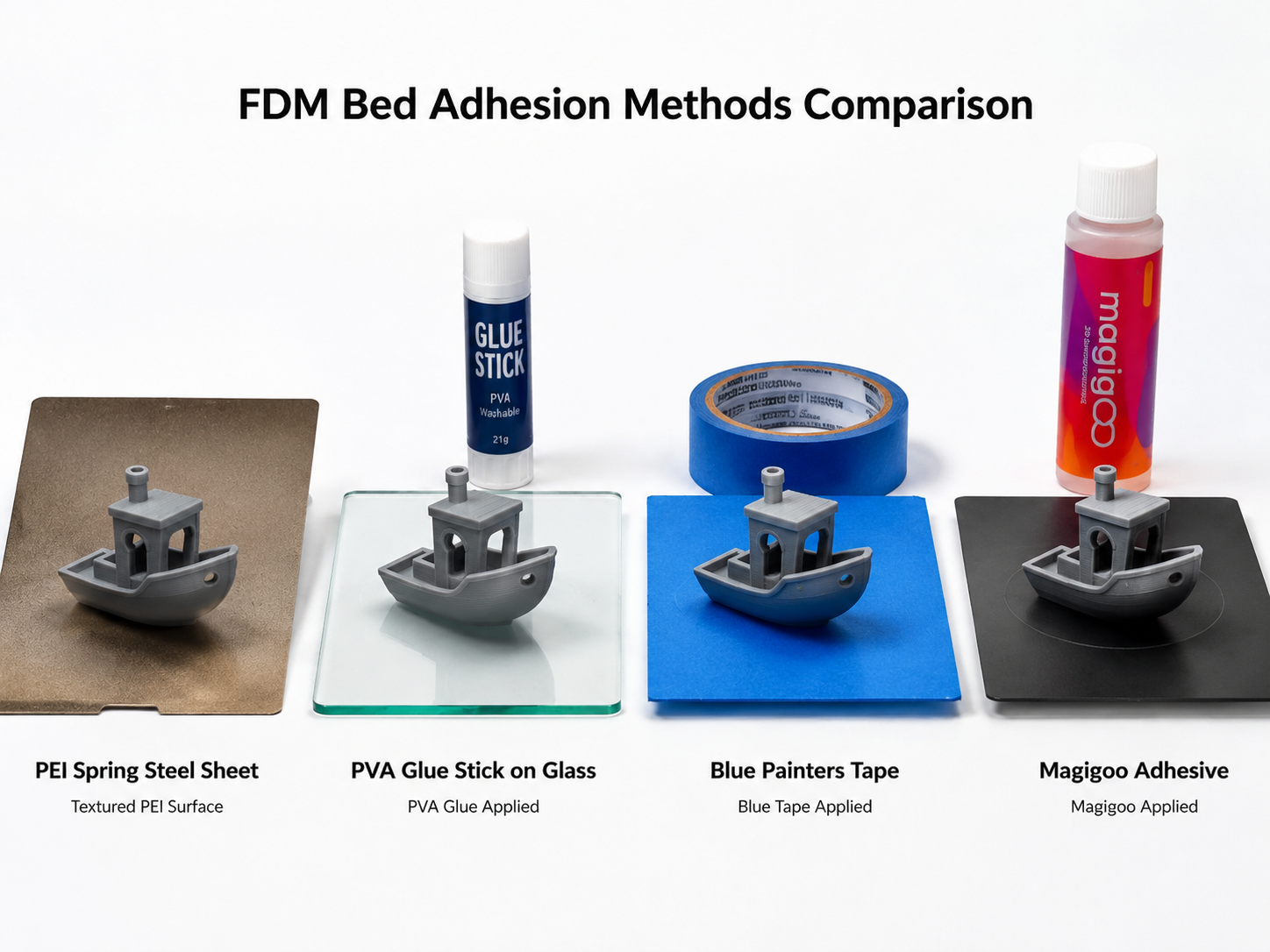
Fix #1: Bed Preparation & Adhesion
The single most effective warping countermeasure is maximizing first-layer adhesion. A part that bonds perfectly to the bed cannot lift — regardless of internal stress.
Bed Surface Selection by Material
| サーフェス | 最適 | Adhesion Strength | リリース | 耐久性 |
|---|---|---|---|---|
| Smooth PEI (spring steel) | PLA, ABS, ASA, PETG, PC | ★★★★★ | Flex plate — pops off when cooled | Excellent (100s of prints) |
| テクスチャ加工PEI | PETG, TPU, PLA | ★★★★☆ | Flex plate — easy release | 素晴らしい |
| Garolite (G10/FR4) | Nylon (PA), PC, ABS | ★★★★★ | Self-releases when cooled | 非常に良い |
| Glass + adhesive | ABS, ASA (with glue stick/PVA) | ★★★☆☆ | Water-soluble glue — soak off | Indefinite (glass), replenish glue |
| BuildTak または類似製品 | General purpose | ★★★★☆ | Moderate — may require scraping | Good (20–50 prints) |
| PP tape / PP sheet | PP (only PP bonds to PP) | ★★★☆☆ | Peel off | Disposable (single-use) |
Quick Adhesion Checklist
- Clean the bed — Isopropyl alcohol (90%+) wipe before every print; dish soap + warm water weekly for PEI
- Level the bed — Automatic bed leveling (BLTouch, CR Touch) is not optional for warp-prone materials; run mesh before every job
- Set Z-offset correctly — First layer should be slightly squished (0.1–0.15 mm lower than slicer default); too high = no adhesion
- Use adhesive where appropriate — PVA glue stick for ABS/ASA on glass; Magigoo PA for nylon; hairspray as a last resort
- Preheat soak — Let the bed sit at target temperature for 5–10 minutes before starting print; thermal expansion stabilizes
- No drafts — Close windows, turn off ceiling fans, avoid HVAC vents near printer
Fix #2: Enclosure & Thermal Management
An enclosure is the single biggest upgrade you can make for warp-prone materials. It traps heat around the print, reducing the thermal gradient between layers and allowing the entire part to cool gradually — rather than the top layers quenching to room temperature while the bottom stays at bed temperature.
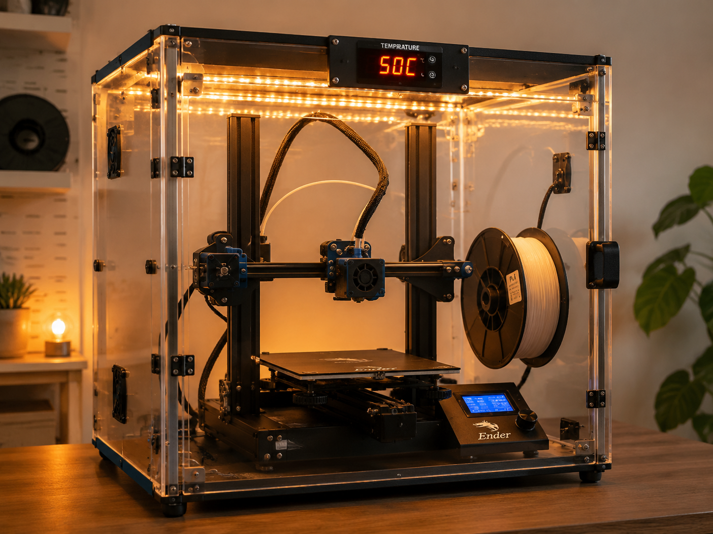
| Enclosure Type | Chamber Temp (Typical) | コスト | Materials Enabled |
|---|---|---|---|
| DIY cardboard / photo tent | 30–40°C | $0–$30 | ABS (small parts), ASA |
| Soft fabric enclosure (Creality, Comgrow tent) | 40–50°C | $40–$80 | ABS, ASA, PC (small–medium) |
| Rigid panel enclosure (acrylic/aluminum) | 50–65°C | $100–$300 | ABS, ASA, PC, Nylon (moderate) |
| Actively heated enclosure | 65–120°C | $500+ | PC, Nylon, PEEK, PEI, PPSU |
Key tip: Even a passive enclosure — just a draft shield — can reduce warping by 60–80% for ABS and ASA. If you’re only printing PLA or PETG, an enclosure can actually cause heat creep issues in the hotend; leave the door open or top off for those materials.
Fix #3: Slicer Settings That Fight Warping
| セッティング | 推奨事項 | Why It Works |
|---|---|---|
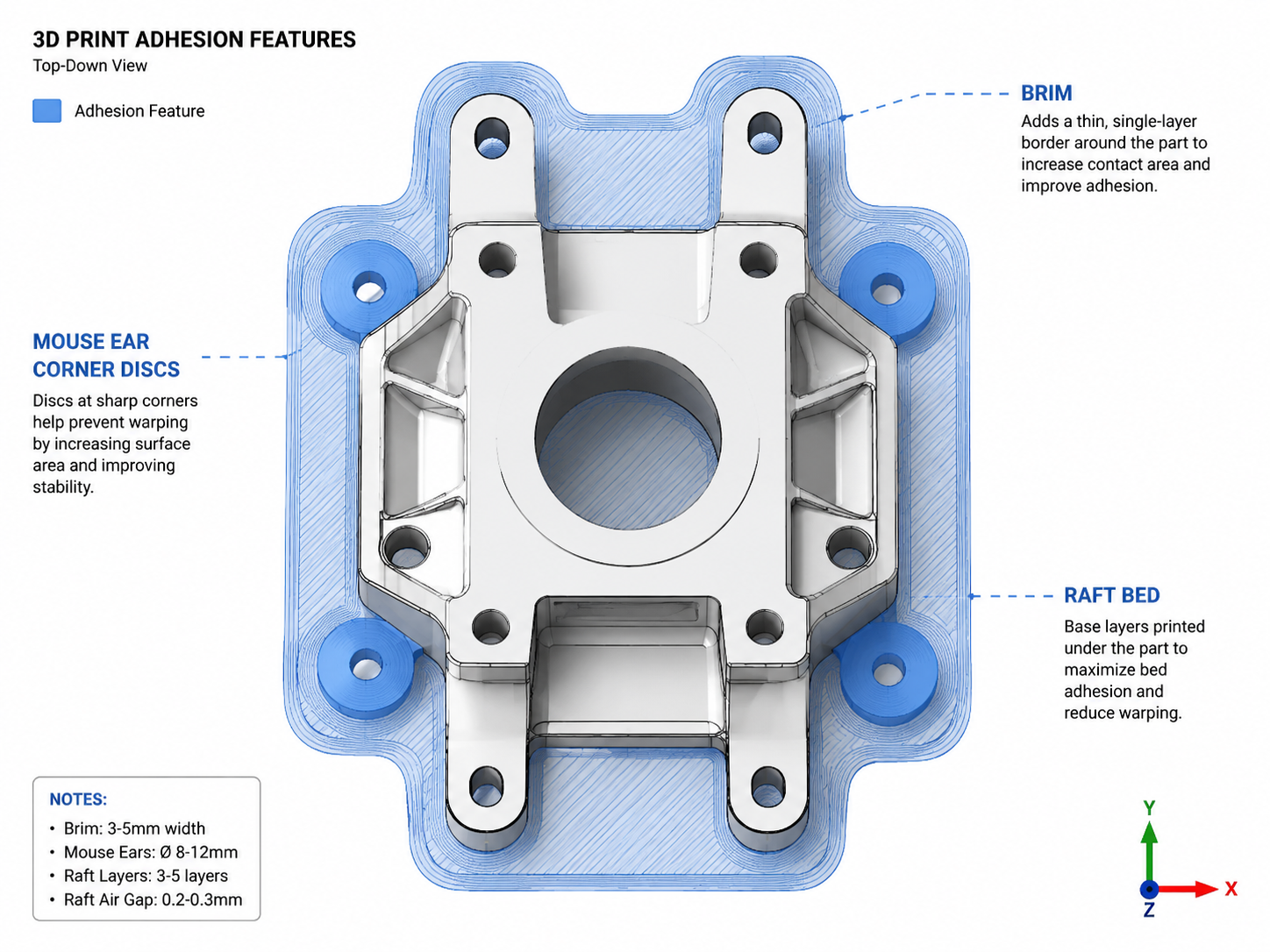
| Brim | 5–10 mm width, 0 mm gap | Increases effective bed contact area by 300–500%, distributing corner stress over a larger footprint |
| Raft | 2–3 layers, 0.2 mm air gap | Absorbs thermal stress in the raft rather than the part; last resort for extreme materials (PC, Nylon) |
| Mouse ears / corner discs | 8–12 mm diameter discs at all sharp corners (CAD or slicer plugin) | Rounds sharp corners at the bed interface; stress concentration reduced by 60–80% |
| First layer height | 0.2–0.3 mm (thicker than default) | Thicker first layer tolerates slight bed unevenness and increases extrusion volume for better adhesion |
| First layer speed | 15–25 mm/s (slow) | Gives filament time to bond to bed surface; fast first layers rip up before adhesion sets |
| First layer width / extrusion | 120–150% extrusion width | Wider, thicker first-layer lines create stronger mechanical bond with bed texture |
| 冷却ファン | OFF for first 3–5 layers; 10–30% max for ABS/ASA/PC | Part cooling fan is a localized draft — the enemy of warp-prone materials |
| Infill density | 15–25% (lower is better for warping) | Dense infill adds material volume → more shrinkage stress. Use gyroid pattern for even stress distribution |
| Wall count / perimeters | 2–3 walls (standard); avoid excessive perimeters | More walls = more material shrinking; balance with infill |
Fix #4: Design for No-Warp
Sometimes the best fix happens in CAD, not in the slicer. If you control the part design, these changes eliminate warping at the source:
- Fillet or chamfer all bed-contact corners — Replace sharp 90° corners with minimum R3 fillets; stress concentration drops exponentially with radius
- Avoid large flat bottom surfaces — Add ribs, recesses, or texturing to break up continuous bottom areas larger than 100×100 mm
- Thin-wall hollowing — Thick solid sections (>5 mm) retain heat longer, increasing thermal gradient; core out thick areas where structurally acceptable
- Balanced wall thicknesses — Uneven wall thicknesses cool at different rates, creating warping vectors that twist the part
- Split large parts — A 300 mm flat plate will warp; two 150 mm plates joined mechanically will not. Design for assembly.
- Orient for minimal bed footprint — Tall, narrow parts warp less than short, wide ones because there’s less bed-contact area to peel
Troubleshooting Flowchart: Systematic Warping Diagnosis
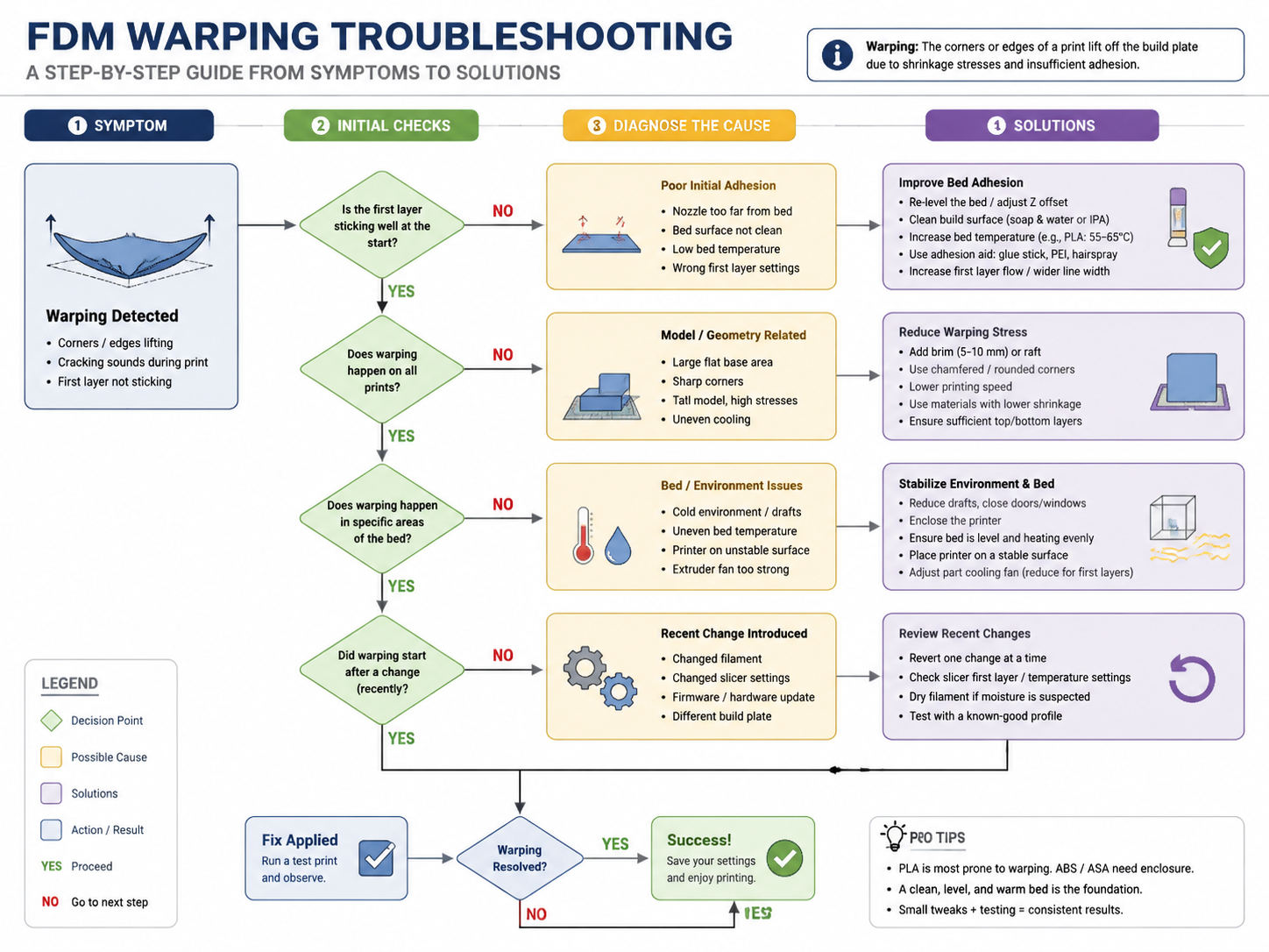
| 症状 | 考えられる原因 | First Action | If Not Fixed |
|---|---|---|---|
| Corner lift (all corners) | Bed adhesion insufficient | Clean bed + increase bed temp by 5°C | Add brim + enclosure |
| One corner lifts (others fine) | Bed leveling uneven; draft from one direction | Re-level bed; add mouse ears at that corner | Block draft source |
| Part completely detaches mid-print | Severe adhesion failure or nozzle collision | Clean bed; check Z-hop enabled (0.2 mm); reduce bed temp 5°C (elephant foot overload) | Switch to raft |
| Warping starts at layer 10+ | Internal stress accumulation beats adhesion over time | Reduce infill %; enable enclosure; reduce fan speed | Switch to lower-warp material |
| Delamination + warping together | Layer adhesion poor (low nozzle temp) | Increase nozzle temp +10°C | Dry filament (moisture reduces layer bonding) |
| Warping only with specific filament brand | Material formulation difference | Run temp tower; adjust bed temp ±10°C | Try different brand or add adhesion promoter |
Advanced: Warping-Resistant Material Alternatives
If you’ve exhausted every fix and your part still warps, the material itself may be the problem. Consider these lower-warp alternatives that deliver similar mechanical properties:
| Warp-Prone Material | Lower-Warp Alternative | Trade-off |
|---|---|---|
| ABS | ASA-CF (carbon-fiber filled) | Higher cost; abrasive — needs hardened nozzle |
| ナイロン(PA6) | PA12-CF or PA6-CF (carbon-fiber nylon) | CF-filled variants shrink 60–80% less; cost 2–3× higher; hardened nozzle required |
| PC (polycarbonate) | PC-ABS blend or PC-CF | PC-ABS reduces warping dramatically; slightly lower HDT |
| PP | PP-GF (glass-filled polypropylene) | Glass fiber reduces shrinkage by ~50%; still needs PP adhesion strategy |
When to Call It: Accepting Warping as a DFAM Constraint
FDM has inherent limitations. If you need sub-0.05 mm flatness across parts larger than 150 mm, consider these alternatives:
- Print oversized + CNC post-machine — Leave 0.5–1 mm stock on critical surfaces, then machine to final tolerance
- Print in sections + bond — Split large parts into smaller, warp-resistant segments; solvent-weld (ABS/ASA) or epoxy-bond
- Switch to SLS or MJF — Powder-bed fusion technologies have near-zero warping because the powder bed acts as a uniform thermal environment; nylonplastic.com offers MJF services for production-grade nylon parts with ±0.3% dimensional accuracy
Need warp-free engineering parts? Our MJF (Multi Jet Fusion) service produces production-grade nylon parts with ±0.3% dimensional accuracy and zero warping — no enclosure, no brim, no troubleshooting required. お問い合わせ for a quote or upload your CAD file for instant DFM feedback.
関連記事
よくある質問
当社の ポリプロピレンとナイロンの比較 詳細な等級区分および物件データについては。.
Why do 3D printed parts warp?
Warping comes from uneven cooling and internal shrinkage stress. Large flat areas, sharp corners, poor bed adhesion, low chamber temperature and high-shrink materials can make the problem worse.
How can 3D print warping be reduced?
Use stable bed preparation, suitable bed temperature, an enclosure, controlled cooling, a brim or corner anchors, dry filament and an orientation that reduces large stressed areas.
Is more bed heat always better?
No. Too much bed heat can soften lower layers or make removal harder. The goal is a stable thermal gradient and reliable adhesion for the specific material and bed surface.
How does filament moisture affect warping?
Wet filament can create bubbles and uneven extrusion while reducing layer adhesion. Dry nylon, PC, PETG and other moisture-sensitive materials before printing and keep them dry during long jobs.
Should I use a brim or a raft?
Use a brim first. Rafts consume more material and time and can leave a rough bottom surface; reserve them for cases where bed preparation, enclosure control and a brim still fail.
Does a heated chamber eliminate all warping?
A stable heated chamber reduces thermal gradients, but it does not remove every risk. Crystallization, moisture, geometry, bed adhesion and material-specific shrinkage still need to be controlled.
Request a 3D Printing Warping Review
Send the material, printer, chamber and bed conditions, part dimensions, orientation and photos of the failure for a focused troubleshooting review.