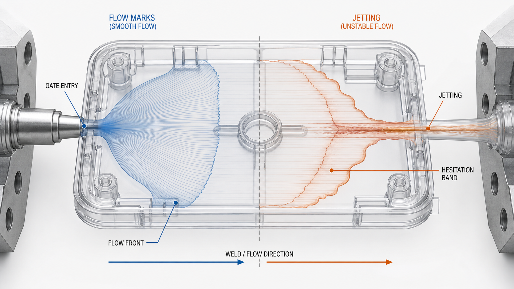
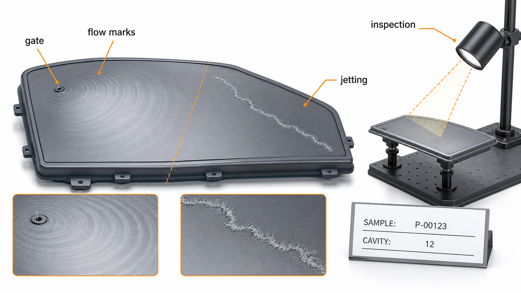
Flow marks and jetting in injection molding are surface-flow defects, but they do not have the same mechanism or the same correction. Flow marks usually appear as bands, rings or gloss changes that follow the advancing flow front. Jetting is a snake-like or worm-shaped streak created when the melt leaves the gate as a narrow stream, travels without contacting the cavity wall, and then folds back into the rest of the flow. Both can be cosmetic failures, and jetting can also create a weak interface or an obvious directional mark.
For a buyer, the first step is to confirm the symptom and locate it against the gate, flow path and cavity. A supplier should not change injection speed, melt temperature or packing pressure from a photograph alone. The useful diagnosis connects the visible mark to a cavity number, material lot, short-shot sequence, gate geometry, venting condition and approved cosmetic limit. That evidence separates a correctable process condition from a gate or part-design problem.
How to distinguish flow marks from jetting
| Observed feature | More likely mechanism | First confirmation |
|---|---|---|
| Broad bands or gloss changes that repeat with the flow front | Cooling or shear history changing as the surface freezes | Compare gate distance, fill time, mold temperature and light-angle inspection |
| Thin snake-like streak beginning directly at the gate | Free jet leaving the gate before it spreads against the cavity wall | Inspect the gate-to-wall direction and make a short-shot progression |
| Mark only at the end of fill with a dark edge | Trapped gas, poor venting or rapid local compression | Compare with the burn-mark and venting evidence at the same cavity location |
| Ring around a boss or insert | Hesitation, local cooling or a flow-front restart | Review wall transition, insert clearance and fill-front timing |
| Surface line that changes with resin lot or moisture | Viscosity, degradation or volatile-related flow variation | Check exact grade, drying record, lot and measured moisture |
Use the common injection molding defects guide for a broad triage matrix, then use the injection mold gate design guide when the mark begins at a gate or gate change is being considered. The weld-line guide helps separate a flow-front meeting line from a streak created at gate entry. This page focuses on flow marks and jetting so corrective action can be assigned to the right evidence.
Cause-to-evidence matrix
| Cause group | Evidence to collect | Correction direction | Risk if changed blindly |
|---|---|---|---|
| Material viscosity or moisture | Resin grade, lot, drying temperature/time, moisture reading and regrind record | Restore the approved material condition and confirm the supplier range | Temperature changes may hide degradation or create a new color/odor issue |
| Injection speed and profile | Fill time, stage positions, peak pressure and mark location by shot | Use a controlled speed profile that keeps the flow front attached and stable | A slower fill can increase hesitation, while a faster fill can increase shear |
| Gate type, size and entry direction | Gate vestige, gate land, gate thickness, wall direction and short-shot images | Spread the melt into the wall or redirect the entry with a DFM-approved gate concept | Gate repair can move the defect, alter pack balance or change cosmetics |
| Mold and surface temperature | Measured mold-surface temperature at the gate and affected zone | Reduce premature skin freezing and stabilize thermal balance | Higher temperature may increase cycle time, flash or material degradation |
| Wall thickness and impingement | Wall map, gate-to-wall distance, ribs, bosses and flow obstruction | Give the jet a nearby wall or use a balanced thickness transition | Adding material without checking sink and shrinkage can create a second defect |
| Venting and end-of-fill conditions | Defect location, vent land, trapped-air evidence and cavity comparison | Improve gas escape and confirm the end-of-fill flow pattern | Venting changes must preserve parting-line integrity and flash limits |
Mark location is often more valuable than the defect name. A line that appears at the same distance from the gate in every shot points to flow-front history or geometry. A line that changes with cavity, lot or barrel recovery points to variation in the material or process. A line that appears only on one cavity can justify a cavity-specific gate, vent, insert or cooling inspection before the entire mold is changed.
Diagnostic sequence for a real production issue
- Confirm the surface symptom. Photograph the part under a controlled light angle, mark the gate and flow direction, and state whether the requirement is appearance-only or functional.
- Identify the sample. Record mold, cavity, machine, resin grade, lot, color, shot number, cycle time and operator change.
- Run a short-shot sequence. Capture several fill percentages without packing to see whether the mark begins at gate entry, a hesitation zone, a rib, an insert or the end of fill.
- Compare cavities. Use the same material and setup so a cavity-specific restriction or vent condition is not hidden by averaging.
- Check the material state. Confirm drying, sealed storage, purge history, color dosing and residence time. For nylon and other moisture-sensitive grades, record actual moisture rather than only dryer setpoints.
- Check the tool interface. Inspect gate land, gate edge, runner balance, vents, parting-line condition, inserts and the surface finish in the affected region.
- Change one controlled variable. Record the starting condition, the single change, the sample range and the surface response before selecting a correction.
A short-shot sequence should be retained with the trial record. It shows whether the flow front attaches to the cavity wall or enters as a free stream. It also helps distinguish jetting from a weld line, because a weld line is normally created when separated fronts meet after flowing around a feature, while jetting starts at an uncontrolled gate entry and can leave a narrow, irregular trail.
Process corrections and their limits
Injection speed should be treated as a flow-front control variable, not a universal cure. If the gate is small or the melt is too cold, a very slow fill may freeze the gate-side skin and create visible bands. If the gate directs a free stream into open space, simply increasing speed may make the jet more energetic. A staged profile can be useful: reduce the initial gate-entry velocity to promote wall contact, then use a stable fill speed after the flow front is established. The correct profile depends on gate, resin, wall thickness and cosmetic requirements.
- Compare fill time and peak pressure with the approved process window.
- Measure melt and mold-surface temperatures; do not treat barrel display values as actual melt temperature.
- Confirm V/P transfer is repeatable and not occurring before the required cavity fill state.
- Use part weight and surface response to evaluate packing changes, even though packing is rarely the first correction for a gate-entry jet.
- Check screw recovery, cushion and non-return-valve repeatability when the mark varies from shot to shot.
- Keep material drying, purge and color-dosing conditions fixed while comparing process trials.
Process changes should be accepted only when the improvement repeats across consecutive shots and does not create flash, sink, warpage, burn marks, gloss variation or dimensional drift. A visually improved single sample is not enough for production approval.
Gate, mold and DFM corrections
Jetting often requires a flow-path correction when the process window cannot keep the melt attached to the cavity wall. Candidate changes may include a fan gate, tab gate, larger gate, different gate land, a gate moved toward a thicker region, or an intentional impingement target. The choice should be reviewed against gate vestige, packing balance, weld-line location, fiber orientation, ejection and cosmetic zones.
For flow marks, review abrupt thickness changes, ribs, bosses, inserts and long thin flow paths. A cavity that freezes too quickly can produce hesitation bands even when the gate itself is acceptable. Cooling should be checked around the affected surface, and venting should be reviewed when the mark appears near the end of fill or is accompanied by a darkened edge. A mold-flow study can compare gate and fill concepts, but the final decision should use the actual tool, resin and customer acceptance sample.
Acceptance and supplier handoff checklist
- Define cosmetic zones, viewing distance, light condition and approved boundary samples.
- Mark gate location, flow direction and the exact defect area on the part photo.
- Provide CAD, controlled drawing, wall-thickness map and annual volume.
- State resin manufacturer, grade, color, reinforcement, lot and drying condition.
- Request cavity-specific short shots, process traces, gate dimensions and vent observations.
- Record fill time, transfer point, peak pressure, melt temperature, mold-surface temperature, cushion and cycle time.
- Agree whether the acceptance sample is free of flow marks, limited to a defined zone, or permitted within a visual boundary standard.
- Approve any gate or DFM correction with a controlled sample set and dimensional review.
When requesting an RFQ or troubleshooting review, send part photos, the resin and grade, cavity number, mold revision, current process sheet, defect rate, annual volume, drawing, cosmetic standard and the assembly consequence. We can then separate a gate-entry issue from a material or process variation and recommend the least disruptive validation path.
When a Process Adjustment Is Not Enough
| Observed Pattern | First Evidence to Check | Likely Next Review |
|---|---|---|
| Mark begins at the gate and snakes across the surface | Gate entry, jet length, short-shot sequence and initial melt temperature | Gate land, gate direction, fill profile and local wall transition |
| Parallel bands follow a broad flow front | Flow length, hesitation, mold-surface temperature and wall thickness | Cooling balance, fill-speed profile, venting and DFM |
| Only one cavity shows the mark | Cavity number, gate dimensions, vent condition and cavity pressure | Cavity-specific repair, balance or maintenance |
| Appearance changes after material handling | Resin lot, color, drying record, moisture and regrind history | Material control before changing the mold |
Jetting is usually a gate-entry and free-jet problem; flow marks can also come from hesitation, cooling, thickness changes or surface-temperature variation. The practical mistake is to adjust temperature or speed without recording where the mark first appears. A short-shot sequence and cavity map usually provide more useful direction than a single finished sample.
How Nylon Plastic Supports Defect Troubleshooting
Nylon Plastic connects material selection, modified nylon grades, injection molding and inspection when a visual defect is being investigated. For PA, PA-GF20 and PA-CF30, the review should include drying, fiber orientation, gate wear, cosmetic boundaries and the actual acceptance sample.
- Separate a resin or moisture change from a gate, vent, cooling or geometry issue.
- Define the cosmetic zone, viewing condition and boundary sample before a correction is approved.
- Validate the least disruptive correction on production-intent material and the affected cavity.
A flow marks vs jetting comparison should start with defect location and flow-front evidence, then trace the result back to gate design and process history.
関連記事
よくある質問
What is the fastest way to separate flow marks from jetting?
Map the defect against the gate and flow direction, inspect under controlled lighting and run short shots. The first appearance often identifies gate entry, hesitation or end-of-fill behavior.
Can the problem be fixed by process settings alone?
Sometimes. Material condition, fill profile, melt temperature and mold-surface temperature can stabilize a marginal process. A persistent gate-origin mark may require DFM or gate review.
When does this problem require a mold modification?
Consider mold work when a documented process window cannot meet the cosmetic limit, the defect is tied to gate geometry or the process correction creates another defect or unacceptable cycle time.
What should a supplier receive before troubleshooting?
Provide photos, CAD, the controlled drawing, resin and grade, cavity and machine information, drying and process records, annual volume, cosmetic standard and the affected assembly feature.
Can wet nylon cause flow marks or jetting?
Yes. Moisture can create bubbles, splay, unstable viscosity and surface streaks that resemble a flow defect. Confirm pellet moisture and drying history before changing the gate.
Request a Flow-Defect Review
Send defect photos, the gate location, resin and grade, cavity data, current process records, cosmetic standard and annual volume for a targeted review.