面取りおよびフィレット設計の概要
Use a chamfer where a flat lead-in guides a mating part. Use a fillet where a smooth transition spreads load at a corner. When both functions matter, dimension the lead-in and the loaded root separately.
A chamfer replaces an edge with a flat face. A fillet replaces a sharp corner with a radius. Both affect the drawing, the mold and how the part fits after molding.
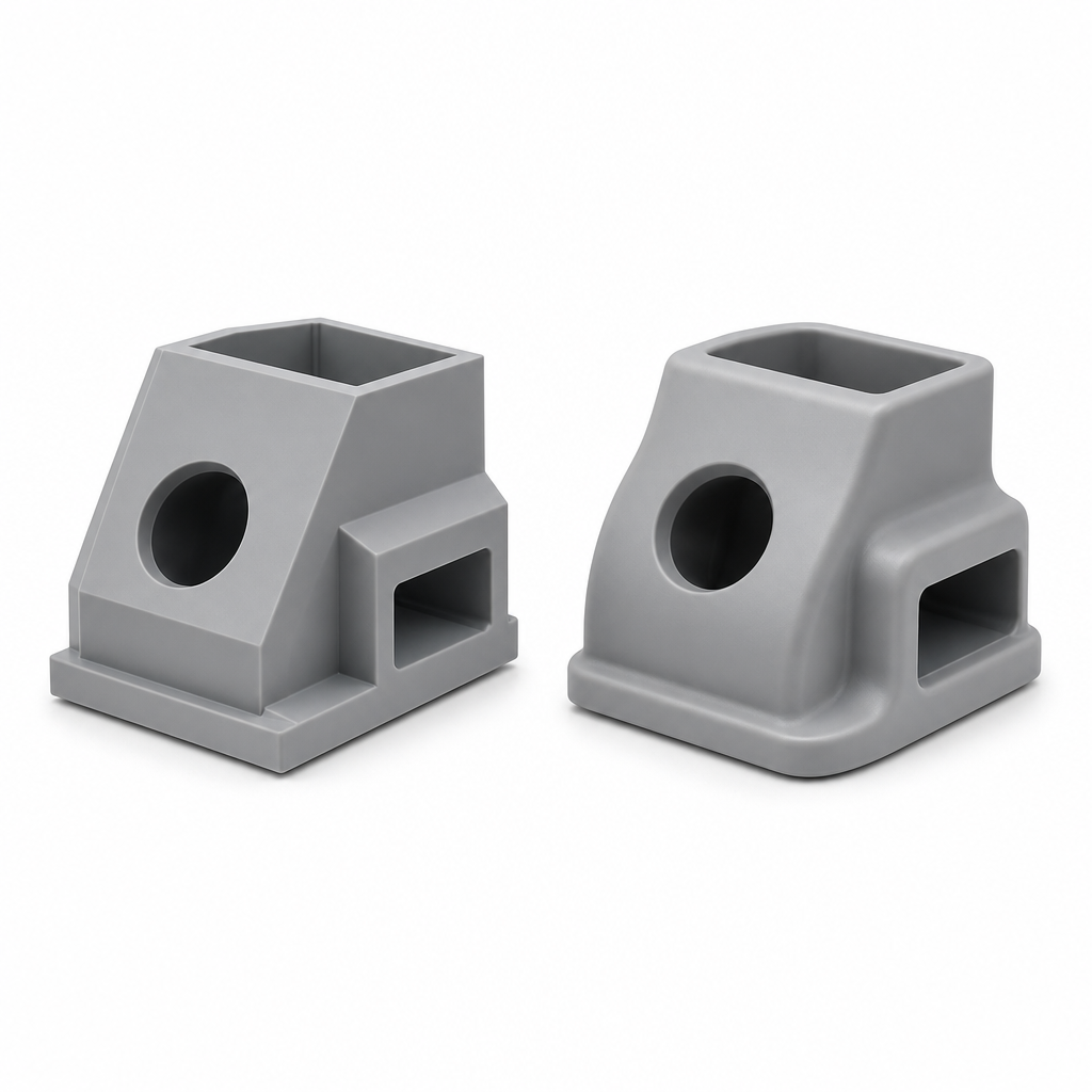
Start with what the edge does in the assembly. Then review pull direction, material and mold access before agreeing dimensions or acceptance criteria.
面取りとフィレットの使い分け
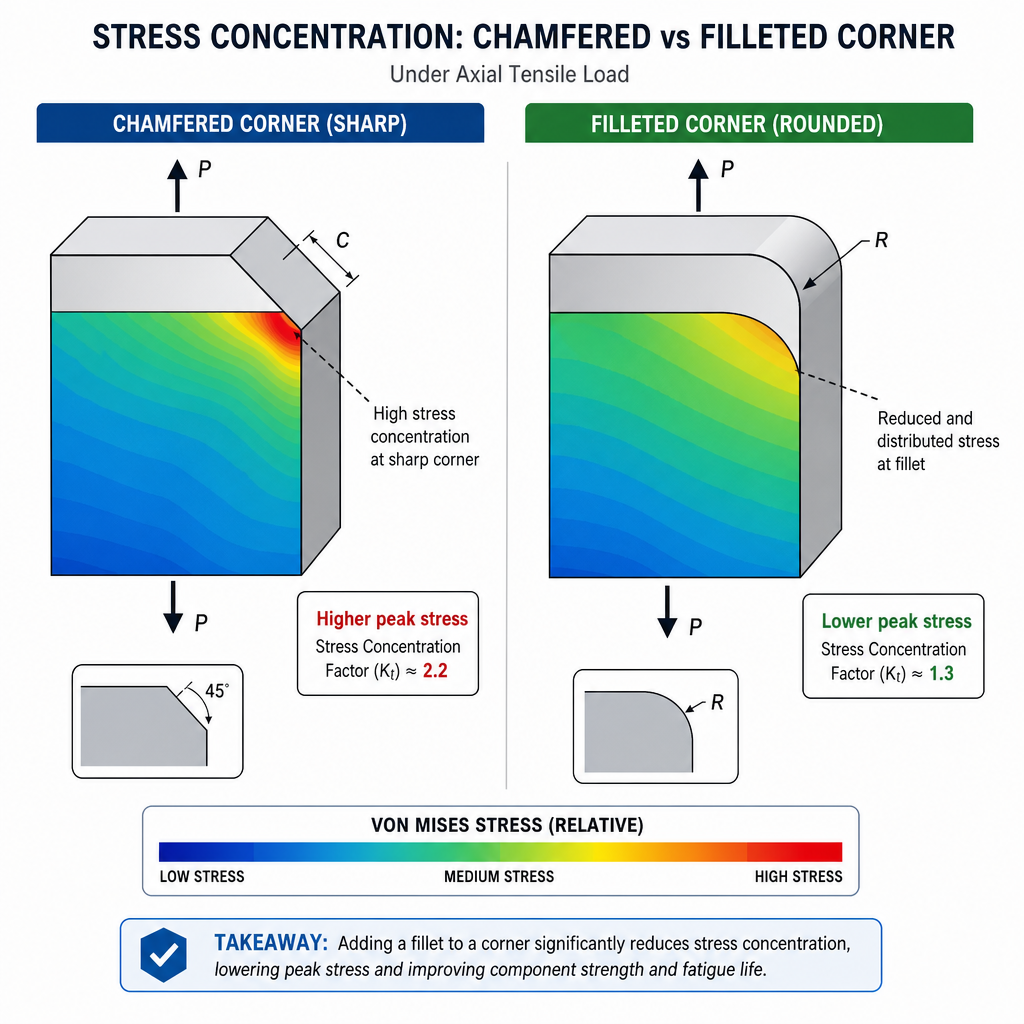
A rounded transition is often useful at the root of a loaded feature. Check the resulting wall section and clearance to adjacent faces before increasing the radius.
A chamfer can provide a defined assembly lead-in or break an exposed edge. Specify which face controls fit and check the mating part’s worst-case offset and engagement.
For a clip or enclosure joint, compare the corner decision with the assembly requirements in the snap-fit design guide.
Fillets at Loaded Corners
The stress concentration factor Kt describes local stress relative to nominal stress for a defined geometry and load. An internal radius can reduce the concentration at a loaded corner. The actual result depends on geometry, loading and material behavior.
Review inside and outside radii together where a wall turns. This helps preserve a consistent section and limits local thickening. See the Protolabs injection molding design guide.
| Edge condition | 設計レビュー | Verification |
|---|---|---|
| Loaded internal corner | Compare the root radius and surrounding section. | Check service loading, fatigue where applicable and first samples. |
| Corner through a wall | Review the inside and outside radius together. | Check for local thickening and sink. |
| Mating lead-in | Use a chamfer where a defined ramp aids entry. | Check mating offset, insertion and retention. |
Mold Fill and Wall Transitions
A smooth change in wall section can help filling. Check the final geometry for thick areas where sink or warpage can affect the part.
Review the edge alongside the gate, melt path and venting. Inspect the first molded samples for short fill, weld lines and appearance at functional edges.
Draft and Edge Geometry
Draft and edge treatments interact because they share the same tool release geometry. Inspect the CAD model in the proposed pull direction and check which face defines the controlled dimension.
For a lead-in near the parting line, agree which face controls fit and how flash will be evaluated. A mating sample is useful when insertion and retention matter.
| 特集 | Draft and tooling review |
|---|---|
| Exterior edge | Check tool pull and cosmetic parting-line witness. |
| Internal radius | Check release direction, wall section and cutter access. |
| Lead-in near a shutoff | Agree mating-face dimension and allowed flash. |
| Edge on an undercut | Review mold split, insert or side-action needs. |
レビュー コアおよびキャビティの設計 when checking how the selected edge will be formed and released by the mold.
面取りとフィレットに関する6つの設計ルール
- Mark the loaded root and the direction of force.
- Check the internal and external radius together to control wall thickness.
- Dimension assembly lead-ins relative to the mating face.
- Review draft and cutter access before tooling release.
- Agree how to inspect fit, flash, appearance and edge dimensions.
- Test the corner in the actual assembly when it controls load or retention.
「」を使用してください。 plastic-part tolerance and inspection guide to define which edge dimensions need acceptance criteria.
業界別適用マトリックス
| 用途 | Edge function | Acceptance check |
|---|---|---|
| Snap-fit enclosure | Guide engagement and support a loaded clip root. | Verify insertion and retention on samples. |
| Bracket | Reduce sharp transitions at the loaded root. | Review load direction and part-test criteria. |
| Sealing housing | Protect the seal and define the assembly lead-in. | Check seal fit and permitted flash. |
| Cosmetic cover | Break touch edges and control visible lines. | Use a defined appearance sample. |
Where the edge is also a cosmetic surface, specify the appearance reference using the SPI mold surface-finish guide.
コスト決定の枠組み
What changes the tooling quote?
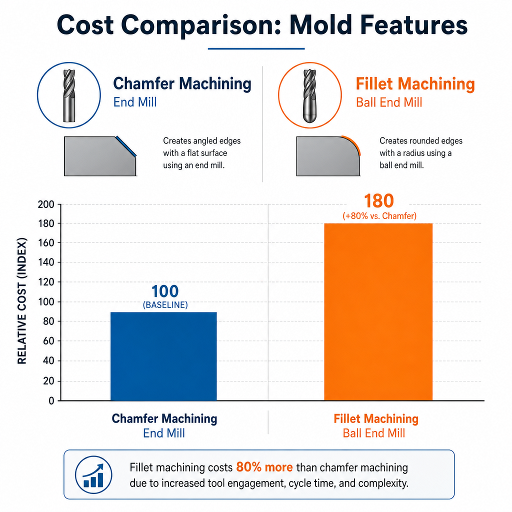
Ask whether the corner changes cutter access, requires EDM or a separate insert, affects the parting line, or adds an inspection step. Compare quote line items for the same geometry and finish.
Resolve corner requirements before releasing the tool. Late changes can affect cavity steel and require new samples or inspection work.
面取り・フィレットのトラブルシューティングガイド
| Observed problem | 復習すべきこと |
|---|---|
| Cracking near a corner | Check the root radius, wall section, weld line and loading. |
| Difficult assembly | Check lead-in, expected offset, flash and mating tolerances. |
| Sink at a transition | Review local section thickness, gate and packing conditions. |
| Scratches after ejection | Review draft, texture and contact with the tool. |
よくある質問
面取りとフィレットの実際の違いは何ですか?
A chamfer is a flat cut across an edge. A fillet is a curved transition. State how the geometry will be dimensioned and inspected.
フィレットを追加することで、プラスチック部品の応力は本当に軽減されるのでしょうか?
A fillet can lower local stress at a loaded internal corner. Validate the result for the actual geometry and service load through analysis or part testing.
射出成形における最小フィレット半径はどれくらいですか?
The practical minimum depends on tool access, finishing, material and inspection capability. Ask the toolmaker to confirm a radius that can be produced and measured reliably.
組み立て用の導入部には、面取りとフィレットのどちらを使うべきでしょうか?
A chamfer gives a defined lead-in. Check the angle and size against the mating part and expected misalignment, then confirm insertion and retention with samples.
関連記事
Request a Molded-Part Edge Review
For chamfer vs fillet decisions on an injection-molded housing, bracket or mating component, send the controlled drawing and the purpose of each critical edge. Nylon Plastic can review the material, part geometry and mold access before quotation.
What should I mark on a drawing for a chamfer or fillet DFM review?
Identify the corner's function: stress relief, assembly lead-in, seal, appearance or tool access. Mark the mating component, load direction, material, permitted radius or edge-break range and the features that must be inspected. The review should distinguish a functional dimension from an optional cosmetic edge, so the quote does not add unnecessary tool work or inspection to every corner.
- Identify load-bearing roots, seal faces, assembly lead-ins, touch surfaces and cosmetic edges. Show both mating parts and mark where design changes are allowed.
- Specify the drawing authority for radius, chamfer distance/angle or a permitted edge-break range, plus datum and inspection access. Identify existing tooling and any features that must remain unchanged.
- State resin and grade, conditioning and service environment, sample and production quantities, destination and timing. Separate design changes, tooling or tool rework, part manufacture and functional inspection in the quote.
製造および配送:
- 精密製造: 30以上のCNCおよび射出成形セルが1つの施設に集結
- ISO 9001:2015 認証取得: 認証済みの品質管理システム、完全な検査報告書
- 15~25日のリードタイム: 迅速な納期に対応し、優先処理オプションもご利用いただけます
- 国際配送: 北米、欧州、アジアへの航空・海上輸送
Agree which corners need dimensional inspection and which need an approved appearance or assembly sample. A generic radius recommendation or predicted stress reduction does not qualify the actual component without its load and geometry.
Planning 射出成形? Include the mating CAD geometry, intended loading and inspection method for edges that control fit or safety.