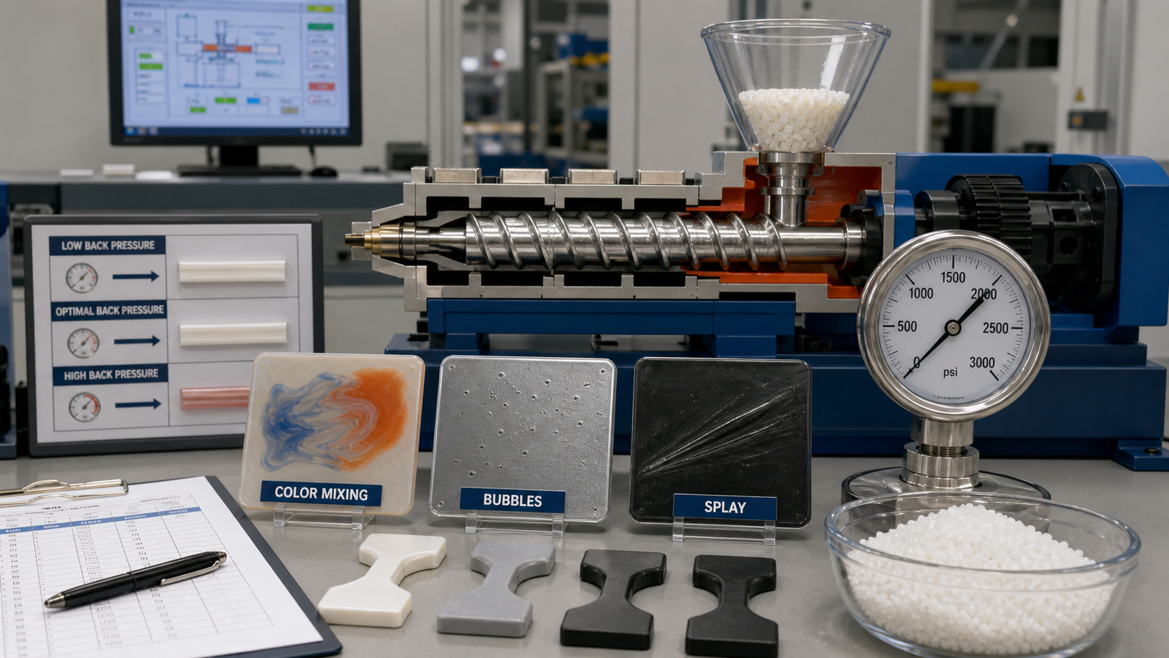
Injection pressure, speed and packing control different parts of the molding cycle and should not be treated as interchangeable settings. Injection speed controls the movement of the melt and the stability of the flow front. Injection pressure is usually a machine or process limit that allows the selected speed profile to run without exceeding the available force. V/P transfer defines when filling changes to packing. Holding pressure then compensates for shrinkage while the gate remains open.
For a buyer, the important question is whether the supplier can show a repeatable relationship between the setting, the machine trace and the molded-part response. A pressure value without the machine size, screw diameter, gate, resin grade and fill time is not enough to reproduce a process. The validation record should show the starting condition, the single variable changed, the resulting pressure or velocity trace, part weight, critical dimensions, appearance and the approved process range.
Velocity control versus pressure control
| Control | What it changes | Useful signal | Common mistake |
|---|---|---|---|
| 射出速度 | Flow-front velocity, shear heating, frozen-layer growth and fill time | Stage profile, fill time, pressure trace and short-shot sequence | Copying a speed number without machine and gate context |
| Injection pressure limit | Maximum force available before the machine limits or stops the fill profile | Peak pressure versus limit and transfer repeatability | Raising the limit to hide a restriction or venting problem |
| V/P transfer | Point at which the machine changes from filling to packing | Screw position, cavity pressure or repeatable transfer signal | Using time alone without checking fill state and part weight |
| Hold pressure | Material compensation after transfer while the gate feeds the cavity | Gate-seal study, weight plateau and dimensions | Extending hold time after gate seal or overpacking the part |
Use the process parameters and setup-sheet guide for the complete process hierarchy. The ゲート設計ガイド explains why gate type and entry direction can make a pressure or speed change appear to work temporarily. The defect diagnosis guide is useful when a setting change creates flash, sink, short shots or warpage.
Fill-speed profiling and flow-front stability
Start by understanding the required flow front. A constant speed may be appropriate for a simple part, while a staged profile is better when the part has a cosmetic face, a thin wall, a long flow path, a weld-line-sensitive feature or a gate close to an insert. The first stage should fill the gate and establish stable wall contact. A mid-fill stage can control orientation and pressure rise. A final stage may be slowed or adjusted near the end of fill to manage air evacuation, cosmetic appearance or pressure response.
Short shots provide the most direct evidence. Capture several fill levels without packing, identify the advancing flow front and mark where hesitation, jetting, a weld line or a gloss change begins. If the flow front changes direction around a rib or insert, record the feature on the sample. This tells the team whether a speed adjustment can address the symptom or whether the gate and geometry must be reviewed.
Do not assume that slower is always safer. A slow flow front may freeze earlier, increase hesitation and create a visible band. A fast flow front may reduce freeze-off in a thin wall but increase shear, trapped gas, burn marks or orientation. The acceptable speed profile is the one that produces repeatable fill and leaves a usable packing and cooling window.
Pressure limits and machine protection
Injection pressure is affected by resin viscosity, melt temperature, gate restriction, wall thickness, flow length, venting, screw diameter and fill speed. A rising pressure trace can indicate normal end-of-fill resistance, but an unexpected rise earlier in the stroke can indicate a cold slug, blocked vent, gate restriction, frozen section, insert shift or material condition problem. Record the point in the stroke where pressure changes, not only the maximum value.
Set the pressure limit high enough to allow the validated fill profile to run with a reasonable margin, but low enough to protect the machine and mold. If the limit is reached, stop and investigate before making a blind increase. Check material drying, actual melt temperature, nozzle and runner condition, gate dimensions, venting, mold alignment, clamp behavior and cavity balance. A machine that reaches its limit on only one cavity needs cavity-specific evidence instead of a larger global limit.
V/P transfer methods
V/P transfer should be based on a repeatable state of the cavity. Screw-position transfer is simple and common, but it should be validated against part weight and pressure. Cavity-pressure transfer can respond more directly to the actual fill condition where suitable sensors and signal quality are available. Time-based transfer may be useful for a stable process, but it is more vulnerable to viscosity, temperature and material-lot variation.
| Transfer method | 強さ | Risk to check | Validation evidence |
|---|---|---|---|
| Screw position | Easy to record and repeat on the same machine | Different machines or screw sizes may not create the same cavity state | Part weight, pressure trace, short shots and transfer repeatability |
| Cavity pressure | Responds to the mold condition at a selected location | Sensor placement, calibration and signal noise can affect the result | Pressure curve, sensor health, weight and dimensional response |
| Hydraulic or machine pressure | Available on many machines and useful as a protection signal | It may not represent cavity fill directly | Correlation with fill state, part weight and peak pressure |
| 時間 | Simple for a stable, well-understood cycle | Viscosity and thermal changes can shift the actual fill state | Repeated shots across lots, cavities and shift changes |
Pack, hold and gate-seal study

After transfer, hold pressure should compensate for material shrinkage without forcing unnecessary stress or flash. Use a gate-seal study to find the point at which additional hold time no longer increases part weight. Then check whether the selected pressure and time meet critical dimensions, sink limits, flatness, sealing, snap-fit function and cosmetic requirements.
Overpacking can move dimensions, increase residual stress, open a parting-line flash condition or make ejection more difficult. Underpacking can cause sink, voids, poor boss strength and dimensional undersize. The correct result is not the highest part weight. It is the lowest stable packing condition that meets function and drawing requirements across the validated sample range.
Cushion, non-return valve and shot repeatability
Cushion is the material remaining in front of the screw at the end of injection. A stable cushion indicates that the shot and non-return valve are behaving repeatably under the selected conditions. A changing cushion can be associated with a leaking valve, inconsistent recovery, an unstable check ring, an incorrect shot size or a process that is close to machine capacity.
- Record cushion for consecutive shots rather than one selected cycle.
- Compare shot weight and part weight when pressure or transfer changes.
- Check recovery speed, back pressure and melt temperature together.
- Investigate a sudden pressure or cushion change before changing hold pressure.
- Keep resin lot, drying condition and purge history traceable during trials.
Defect response matrix
| 症状 | First evidence | Possible adjustment | When to review mold or DFM |
|---|---|---|---|
| ショートショット | Fill time, peak pressure, short shots, material condition and vent map | Stabilize material, fill profile, melt temperature or transfer | Pressure remains high at a gate, thin wall or blocked vent after process checks |
| Jetting or flow mark | Gate-entry short shots and flow-front direction | Adjust gate-entry speed or staged profile | Mark begins as a free stream or gate direction prevents wall contact |
| Flash | Parting line, shutoff, vent, pressure trace and cavity comparison | Review transfer and hold pressure | Flash persists within a stable window or is cavity-specific |
| Sink or void | Gate seal, weight plateau, thick-section map and hold response | Adjust transfer, hold profile or cooling | Heavy geometry or gate location prevents effective packing |
| 反り | Free-state profile, cavity map, cooling data and packing response | Balance fill, packing and cooling | Distortion follows gate, cooling circuit or wall-thickness imbalance |
Setup and validation checklist
- Record resin grade, lot, moisture condition, color and reinforcement.
- Record machine, screw diameter, shot utilization, mold revision, cavity and gate.
- Record fill time, speed stages, peak pressure, pressure limit and transfer method.
- Record cushion, recovery time, back pressure, actual melt temperature and mold-surface temperature.
- Run a gate-seal study before finalizing hold time.
- Measure part weight, critical dimensions, cosmetic zones, flatness and assembly function.
- Compare consecutive shots and all cavities, not only a visually favorable sample.
- Document the approved center, normal range, warning limit and stop limit.
For an RFQ or supplier review, provide the controlled drawing, CAD, resin and grade, gate concept, annual volume, machine constraints, defect photos, current process trace and inspection method. We can then connect pressure and speed changes to the part response and determine whether the next trial should be a process adjustment, a gate review, a cooling review or a DFM correction.
Process Window Decisions That Affect Part Cost
| Decision | What Can Go Wrong | Evidence to Keep |
|---|---|---|
| Fill-speed profile | Hesitation, jetting, shear heat or an unstable flow front | Short shots, fill time, pressure trace, appearance and cavity comparison |
| Pressure limit | The machine hides a restriction by running close to the limit | Peak pressure, transfer state, cushion, clamp margin and repeatability |
| V/P transfer | Underpacking, flash, overpacking or shot-to-shot weight movement | Transfer method, fill percentage, cavity pressure or part-weight trend |
| Hold and gate seal | Sink, void, stress, dimensional drift or unnecessary cycle time | Gate-seal study, weight plateau, critical dimensions and functional samples |
For nylon, a stable process window also depends on the exact grade, reinforcement, color, moisture condition and mold temperature. PA-GF20 and PA-CF30 can change flow resistance, fiber orientation and pressure response, so a setup sheet copied from unfilled PA should be treated as a starting point only.
How Nylon Plastic Supports Process Review
Nylon Plastic has supported modified plastic materials and finished-part manufacturing since 2005. The useful review connects material condition, gate and mold design, process traces, inspection and the intended production volume before a supplier is asked to repeat a setting.
- Compare unfilled PA, PA-GF20 and PA-CF30 against the actual part failure mode.
- Use the same resin, mold revision, cavity, machine and inspection condition when validating a change.
- Define the approved center, warning limit, stop limit and reaction owner in the setup sheet.
Injection pressure speed packing decisions should be tied to the machine trace, gate-seal evidence, part weight and critical dimensions rather than treated as isolated setpoints.
関連記事
よくある質問
Is injection pressure a setpoint or a limit?
It is commonly used as a pressure limit while the selected velocity profile controls filling. Review the pressure trace, transfer state and clamp margin before raising the limit.
How is injection speed selected?
Use short shots, flow-front behavior, pressure, fill time, appearance and the exact resin and gate to select a stable profile. A universal speed is not reliable.
What is V/P transfer?
V/P transfer is the change from velocity-controlled filling to pressure-controlled packing. Validate it with weight, dimensions, flash, sink, pressure and function.
How long should holding pressure be applied?
Hold pressure should continue until the gate seals for the validated material, gate and mold-temperature condition. Confirm with a gate-seal study rather than a default time.
How does cushion affect shot repeatability?
A stable cushion shows that the screw has a repeatable compression and transfer condition. Cushion movement can point to check-ring leakage, inconsistent fill, material variation or an unstable process window.
Request a Process Window Review
Send the drawing, resin and grade, gate concept, current setup sheet, defect data, annual volume and critical inspection requirements for a process review.