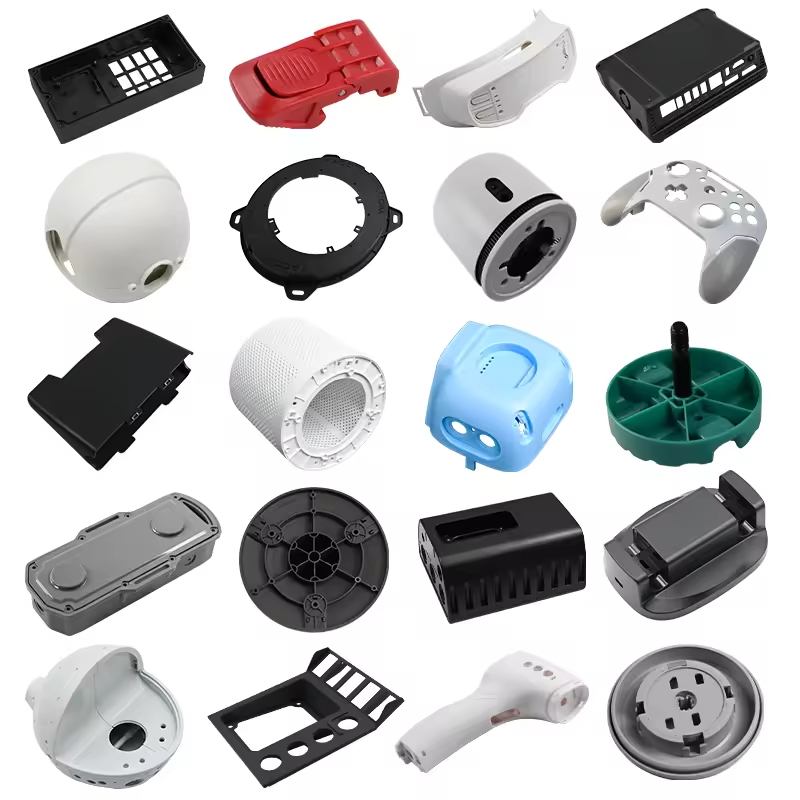
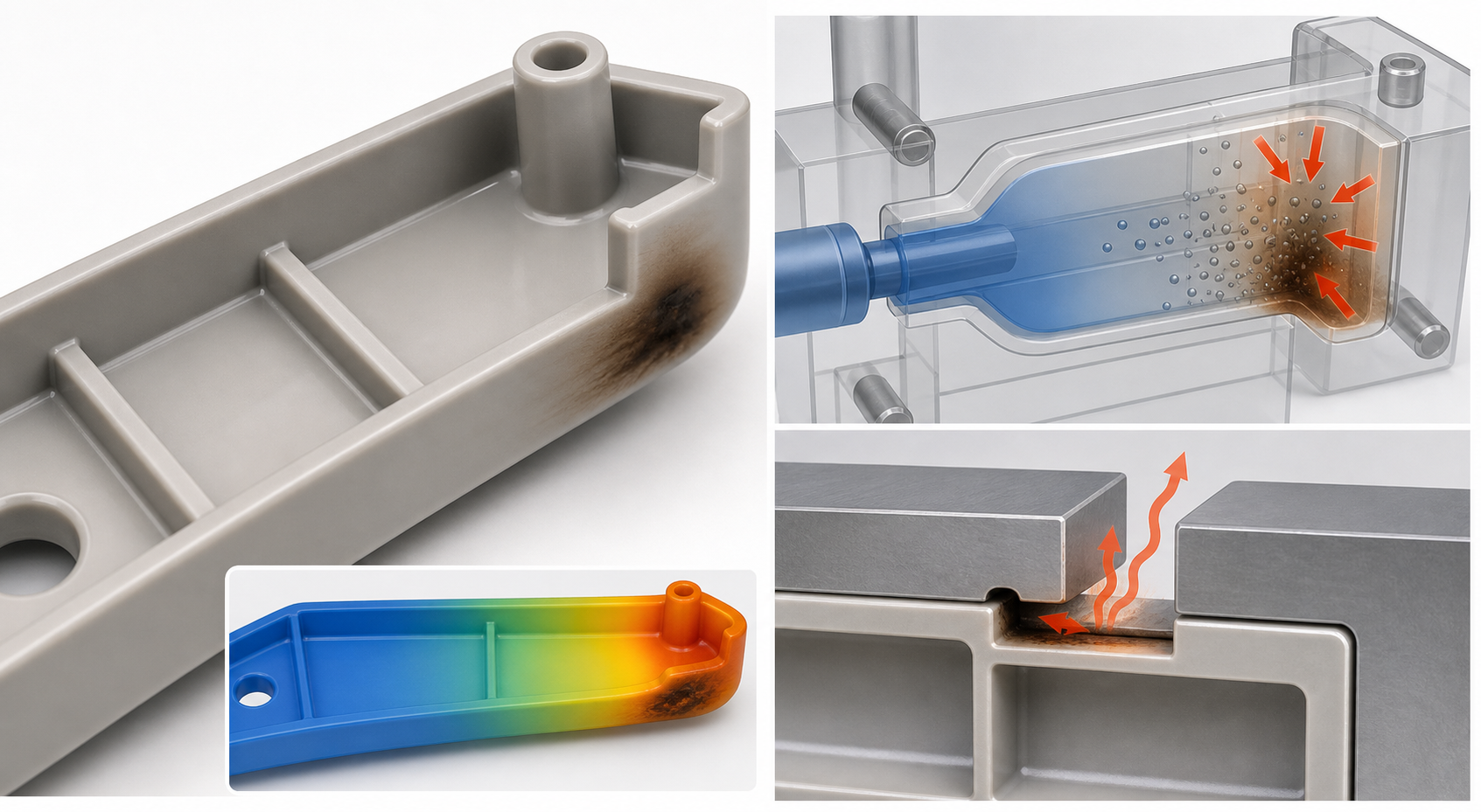
Injection mold venting design must release displaced gas at the actual end-of-fill locations without allowing flash or damaging the parting surface. Venting affects fill pressure, burn marks, diesel effect, weld-line strength, short shots, dimensional repeatability and cavity balance. A vent that works during the first trial but becomes blocked by resin, fiber or condensation is not a production-ready solution.
For a buyer, the venting review should show where air is expected to finish, how gas reaches the exterior, how the vent is cleaned and how the result will be verified. Vent depth should be selected from resin and tool conditions, not copied as a universal number. Review vents with gate, flow direction, ribs, bosses, inserts, parting line, ejection and the approved cosmetic standard.
The engineering function of venting
| Venting objective | What it controls | Evidence to review | Risk when overlooked |
|---|---|---|---|
| Gas release | Pressure and air displacement at end of fill | Flow-end map, short shots and vent path | Burns, short shots, high pressure or weak welds |
| Flash control | Vent depth, land and parting-line sealing | Resin, pressure, blue check and trial flash | Vent flash, mismatch or a vent that cannot be maintained |
| メンテナンス | Gas-path performance over production | Access, cleaning interval, contamination and flow checks | Recurring burns, drift and cavity-to-cavity variation |
| Feature coverage | Air around ribs, bosses, inserts and blind pockets | Flow simulation, feature short shots and local vent map | Dieseling, incomplete fill or weak knit lines |
| Validation | Repeatable fill and surface condition | Burn-location map, pressure, cavity comparison and samples | Process settings hide a mold-interface problem |
Use the burn-mark guide for symptom diagnosis. The parting-line guide explains how vent land and shutoff support interact. The runner and sprue guide is useful when pressure and flow balance affect where air finishes.
Inputs that control vent placement
Map the likely end-of-fill locations from gate position, flow direction, wall thickness, ribs, bosses, inserts and weld-line requirements. Air may finish at a perimeter, corner, rib intersection, blind pocket, slide, ejector or insert. A vent placed far from the actual air trap may not solve the problem, even if it is easy to machine.
Resin viscosity, fill speed, melt temperature, moisture, filler, volatiles and degradation affect gas and pressure. Flame-retardant grades, filled materials and sensitive engineering resins may need special attention to purge, residence time, vent depth and cleaning. A high-speed fill can require better gas relief, while a slow fill can allow the flow front to freeze before air escapes.
- Resin grade, filler, viscosity, moisture, volatile content and melt range.
- Gate, runner, flow direction, fill profile and end-of-fill locations.
- Ribs, bosses, inserts, slides, blind pockets and weld-line areas.
- Cosmetic zones, flash limit, critical dimensions and inspection condition.
- Annual volume, vent-cleaning interval, access, automation and tool life.
- Pressure trace, short shots, burn map, cavity comparison and material record.
Vent geometry and exhaust path

A vent has an entrance at the cavity and a relief path that carries gas away without becoming a flash path. The land, depth, width, length and downstream relief depend on resin, pressure, mold steel, surface and production conditions. The vent should be accessible for inspection and cleaning, and it should not create a sharp cosmetic edge or weaken a shutoff.
Parting-line vents are common where the flow ends at an accessible split. Ejector or insert vents can reach local pockets, but their fit, movement and contamination need control. Porous inserts can help in difficult areas, while vacuum systems may be considered for deep or enclosed geometry when conventional vents cannot provide sufficient gas removal. These options add cost and maintenance, so they should be tied to evidence from the part and trial.
Material and production-volume effects
| Material or condition | Venting concern | Design response | Validation focus |
|---|---|---|---|
| Low-viscosity resin | Small vent clearances can flash easily | Use resin-specific depth, supported land and controlled pressure | Flash map, blue check and cavity comparison |
| Flame-retardant grade | Volatiles and degradation can increase gas or deposits | Review vent area, residence time, purge and cleaning access | Burn location, odor, deposits and pressure trace |
| Glass-filled resin | Fiber/debris can clog or abrade the vent | Use suitable steel and a practical cleaning interval | Long-run vent condition, flash and burn trend |
| Deep rib/pocket | Air can be trapped away from a simple perimeter vent | Add local vent, ejector vent, insert or vacuum path | Feature short shots, weld-line strength and burn map |
| High-volume production | Deposits and wear change performance | Define inspection, cleaning and replacement limits | Process trend, maintenance record and cavity balance |
Tooling options and cost trade-offs
| Option | ベネフィット | Trade-off | Suitable when |
|---|---|---|---|
| Parting-line vent | Simple access and familiar construction | Must balance exhaust and flash control | End of fill reaches a supported split |
| Ejector/insert vent | Reaches local pockets and features | Fit, movement, wear and cleaning | Air trap is remote from the main split |
| Porous insert | Distributed gas relief in difficult geometry | Cost, cleaning, clogging and repair | Conventional vents cannot reach the air trap |
| Vacuum venting | Improves gas removal in enclosed or deep areas | Equipment, seals, timing and maintenance | High-risk air trap or demanding cosmetic/functional part |
Failure modes and corrective actions
Burn marks and diesel effect occur when gas is compressed and heated faster than it can escape. Short shots can occur when pressure rises against trapped air or when the flow front freezes before the pocket fills. Weak weld lines may result from cold fronts or gas at the meeting area. Dimensional variation may appear when cavity pressure and fill timing change with vent condition.
Do not immediately increase melt temperature or injection pressure. First map the burn or incomplete-fill location, run short shots, compare cavities, inspect the vent and review material condition. A process change may reduce the symptom temporarily but can increase flash, degradation or cycle. Vent repair should preserve shutoff support and should be verified by blue check and repeated samples.
Validation at mold trial and production approval
- DFM vent map: mark predicted flow ends, air traps, ribs, bosses, inserts and cosmetic areas.
- Short-shot study: capture fill progression and identify where gas is compressed or the flow front stops.
- Burn-location map: compare surface marks with vent and end-of-fill positions by cavity.
- Pressure/cavity evidence: record fill time, pressure, transfer, weight and cavity variation.
- Vent inspection: verify geometry, land, relief, blue check, access and cleaning method.
- Production run: retain consecutive samples and document performance before and after the maintenance interval.
DFM checklist and RFQ data package
- Provide CAD, drawing, resin, grade, texture, annual volume and tool-life target.
- Mark cosmetic zones, weld-line limits, critical dimensions and end-of-fill concerns.
- Request vent map, resin-specific depth basis, relief path and maintenance access.
- Ask for short-shot, burn-location, pressure, cavity and vent-inspection evidence.
- Define cleaning frequency, flash limit, acceptance sample and repair rules.
- State automation, mold destination and any special vacuum or porous-insert requirement.
For an RFQ, include defect photos, material condition, current process record, CAD, drawing, cavity count and annual volume. We can then determine whether the first action should be venting, material control, fill-profile adjustment, gate review or a part-design correction.
Ask the supplier to distinguish vent geometry from vent-cleaning performance. A correct initial vent can still lose capacity when deposits build up or an ejector vent stops moving freely. The production record should therefore include the vent inspection method, the responsible maintenance step and the evidence used to return the mold to service.
That record is especially important when the defect appears only after several hours, a resin change or a color transition.
Venting Risks Buyers Should Resolve Before Mold Trial
- End-of-fill locations are not identified, so vents are added only after burns or short shots appear.
- Vent depth is copied without checking resin viscosity, filler, parting-line condition, or the supplier’s maintenance method.
- Burn marks are treated as a temperature problem even though trapped gas, air compression, and blocked vents may be the primary cause.
- Venting is validated on one clean trial but no cleaning interval, cavity map, or production reaction plan is defined.
How Nylon Plastic Supports the Project
Nylon Plastic has supported material selection and finished plastic-part manufacturing since 2005. For injection mold venting and fill validation, the useful review connects the drawing, material, tooling or machining route, inspection state, and production plan before a quote is approved.
- Review gate, flow, wall, weld-line, material, and filler direction together before finalizing vent locations.
- Connect mold trials, short shots, burn maps, cavity records, inspection, and maintenance instructions to the production approval package.
- For unfilled PA, PA-GF20, or PA-CF30, account for moisture, viscosity, fiber or additive behavior, and the actual material lot during validation.
関連記事
よくある質問
Why is venting important in injection molding?
Venting allows displaced air and gas to leave the cavity. Good venting supports fill, reduces burn marks and diesel effect, improves weld-line consistency, and can widen the stable process window.
Can poor venting cause short shots?
Yes. Trapped gas can resist the advancing melt and create short shots, burns, hesitation, or weak weld lines. Confirm the location with short shots, flow evidence, and vent inspection.
Does glass-filled nylon change mold venting needs?
It can. Resin viscosity, filler, fiber orientation, moisture, and deposit or wear behavior affect vent performance. Validate the exact PA-GF grade and maintenance interval.
How should mold venting be validated?
Use short shots, burn-location mapping, cavity and pressure evidence where available, vent inspection, repeated trial samples, dimensional and visual checks, and a documented cleaning reaction plan.
Request an Injection Mold Venting Review
Send the part files, flow or gate concept, material, defect evidence, and mold-trial requirements for a venting and fill review.