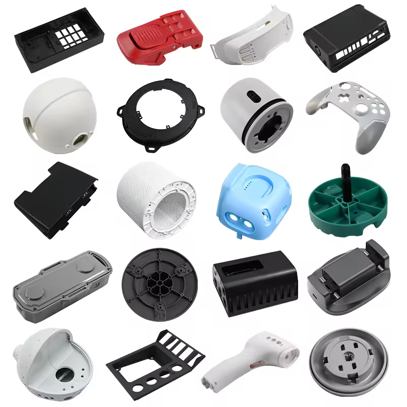
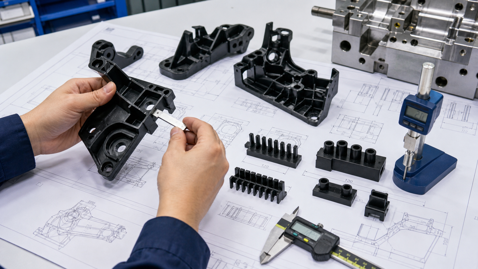
Injection mold ejection design must remove the part after adequate cooling without concentrating force on thin walls, cosmetic surfaces, ribs, bosses or sealing features. The right choice may be ejector pins, sleeves, blades, a stripper plate or ring, air assist, robotic removal, or a combination. Selection depends on part retention, draft, projected area, shrinkage, stiffness, cosmetic zones, automation direction and the temperature at which the part must be released.
For a buyer, the key question is not how many ejector pins a mold has. It is whether ejection force is distributed into supported geometry and whether the witness marks, dimensions, cycle and automation result meet the drawing. Ask for an ejection map, retention-side decision, pin or sleeve locations, return protection, slow-motion trial evidence and the limits for ejection force and witness marks.
The engineering function of ejection
| Ejection requirement | What it controls | Evidence to review | Risk when overlooked |
|---|---|---|---|
| Distributed contact | Force and local stress during release | Ejector map, wall support, ribs, bosses and parting surfaces | Pin push, cracking, whitening or distortion |
| Retention-side control | Which mold half holds the part during opening | Shrinkage, texture, draft, core/cavity balance and opening sequence | Part remains on the wrong side or is pulled across a cosmetic face |
| Cosmetic protection | Visibility and size of ejector witness | Cosmetic zones, boundary sample and pin placement | Visible marks, gloss change or customer rejection |
| Automation compatibility | Repeatable handoff to robot, gripper or conveyor | Part orientation, release height, cycle and sensor location | Part drop, collision, cycle variation or manual intervention |
| Return and protection | Safe mold closing and pin alignment | Return pins, switches, limit blocks and interference check | Pin breakage, mold damage or an unsafe close condition |
Use the draft angle guide when ejection force is being used to compensate for release geometry. The temperature guide explains why a part that is too hot can deform even with a suitable ejection layout. The mold design and mold making page covers the wider tooling review.
Inputs that control ejection
Map where the part grips the core after shrinkage and where the part can accept force. A broad cylindrical core may need a stripper ring or a well-distributed pin pattern. A box with deep ribs may need pins under structural webs or blades placed along reinforced edges. A thin cosmetic panel may need a stripper surface, air assist or a revised retention strategy so the force does not print through the face.
Draft and surface finish determine how much force is needed. Texture can increase retention, while polish direction, vacuum and a rough or damaged core can create drag. Resin stiffness, filler, shrinkage, moisture condition and ejection temperature also matter. Glass-filled grades may resist deformation but increase tool wear; soft TPE can stretch, tear or remain on a textured core.
- Part retention side, draw direction, draft, texture and shrinkage.
- Wall thickness, ribs, bosses, snap features, inserts and unsupported spans.
- Cosmetic, sealing, datum, assembly and visible-witness zones.
- Resin grade, filler, stiffness, temperature and conditioning state.
- Annual volume, cycle target, robot/gripper direction and part handoff.
- Ejector stroke, return system, safety switches, maintenance access and spare parts.
Ejector pins, sleeves, blades and strippers
| Option | 最適な用途 | ベネフィット | Risk or limit |
|---|---|---|---|
| Ejector pins | Supported ribs, bosses, webs and non-cosmetic surfaces | Flexible layout, familiar maintenance and controlled replacement | Pin push, local stress, witness marks and breakage in thin walls |
| Sleeve ejectors | Bosses, cores and cylindrical features | Distributes force around a boss and can support a ring | Requires clearance, alignment, wear control and correct boss geometry |
| Ejector blades | Narrow ribs, slots and elongated features | Fits where a round pin cannot reach the load path | Thin blade can crack, wear or leave a sharp witness |
| Stripper plate/ring | Large rings, housings and broad supported surfaces | Spreads force and can protect cosmetic walls | Higher tool cost, alignment and sealing complexity |
| Air or robotic removal | Parts with suitable air surfaces or controlled automation | Reduces concentrated mechanical marks and supports a clean handoff | Needs air path, sensors, timing and reliable part orientation |
A pin should push into a region that can carry the load. Placing pins directly under a thin cosmetic wall may produce a visible circle or local bulge. Placing them under a rib or boss can distribute load, but the feature must be strong enough and the pin must not create sink or a stress concentration. Sleeves can be useful around bosses, while blades work for narrow ribs if there is enough steel and wear support.
Geometry, support and return protection
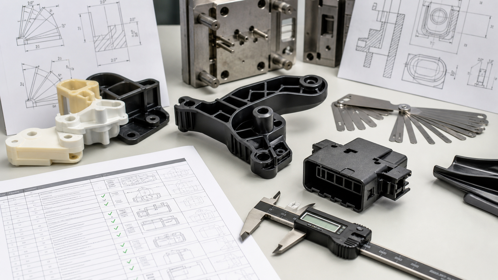
Ejection should be balanced around the center of mass and the expected retention pattern. Uneven force can tilt a part, pull one corner across the core or bend a long wall. The ejector plate should have adequate guidance and support, and pins should return without interference from slides, lifters, inserts, core pins or sensors. A return switch or mechanical protection should confirm that the mold can close only when the ejectors are fully returned.
For multi-cavity tools, compare ejection behavior by cavity. A cavity with a different polish, draft, texture, vent or cooling condition can need more force even when the ejector layout is identical. Record cavity, cycle, ejection sound, part orientation and witness condition during the trial. A single difficult cavity should not be hidden by averaging all parts together.
Material and production-volume effects
| Material or condition | Ejection concern | Design response | Trial evidence |
|---|---|---|---|
| Brittle or glass-filled resin | Low tolerance for concentrated stress and higher tool wear | Support load paths, use suitable pins/sleeves and protect wearing surfaces | Cracks, whitening, pin marks, wear and cavity comparison |
| Soft TPE | Part can stretch, tear or deform around pins and texture | Use broad support, controlled stroke/speed and a stable removal direction | Stretch, tear, recovery, witness and automated handoff |
| Hot ejection | Part stiffness is low and dimensions can move after release | Increase cooling or support area before release where cycle permits | Free-state profile, post-conditioning dimensions and sticking |
| Deep textured core | Retention and vacuum can increase force | Review draft, texture direction, air assist and retention side | Release force, drag, texture damage and surface inspection |
| High-volume production | Pin wear, lubrication, alignment and vent/debris build-up accumulate | Define maintenance intervals, spare pins, wear limits and inspection access | Long-run witness trend and ejection repeatability |
Failure modes and corrective actions
Pin push appears as a circular mark, bulge or local deformation. Cracking can occur at a boss, rib root, insert or brittle corner when ejection force exceeds the feature’s support. Whitening indicates local stress in some resins. Sticking may result from insufficient draft, a hot part, texture, vacuum, poor polish or an undercut. Pin breakage can come from misalignment, insufficient steel, wear, debris or an interference with a moving component.
Corrective action should begin with evidence. Check retention side, part temperature, draft, surface condition, ejection timing, force and cavity pattern. A slower ejector stroke may reduce impact but does not solve a part that is fundamentally locked to the core. Adding pins may spread force, but it can increase witness marks and maintenance. A stripper, sleeve, lifter, air feature or DFM change may be the better solution.
Validation at mold trial and production approval
- DFM review: map retention surfaces, draft, cosmetic zones, support features and automation direction.
- Motion check: confirm ejector, slide, lifter, insert, return and robot paths without interference.
- Slow-motion trial: observe when the part releases and whether it tilts, drags, cracks or remains on the wrong side.
- Witness inspection: compare pin, sleeve, blade or stripper marks with the drawing and boundary sample.
- 寸法チェック: measure critical features before and after conditioning or assembly as specified.
- Repeatability: run consecutive shots from every cavity and verify robot/gripper handoff at the target cycle.
DFM checklist and RFQ data package
- Provide CAD, drawing, resin, grade, texture, annual volume and tool-life target.
- Mark retention side, draw direction, cosmetic zones, critical datums and allowed ejector witness.
- State ejection temperature, cycle target, robot/gripper plan and mold destination.
- Request an ejector map showing pins, sleeves, blades, stripper surfaces and air features.
- Ask for return protection, slow-motion trial, force/witness inspection and cavity comparison.
- Define accepted samples, functional tests, maintenance limits and spare-part expectations.
For an RFQ, show the surfaces that must remain cosmetic or flat and identify where an ejector witness is acceptable. We can then select support points and release hardware around the actual load path rather than adding pins after a sticking problem appears.
Ejection Design: Protect the Part Before the Cycle Is Fast
| Part Condition | Typical Ejection Risk | Design Response |
|---|---|---|
| Deep core or high shrinkage | Sticking, whitening, cracking or excessive force | Review draft, polish, shrinkage direction, lifters and balanced support |
| Thin wall or cosmetic face | Ejector witness, local distortion or visible marks | Distribute force, move pins to supported areas, or consider a stripper system |
| Ribs, bosses or inserts | Local collapse, pin interference or incomplete return | Add support, sleeves, blades, return confirmation and clearance checks |
| Automated take-out | Part drops inconsistently or gripper force changes the shape | Validate ejection timing, robot handoff, cooling state and repeatability |
Fast ejection is not a quality target by itself. The correct system releases the part at a controlled temperature and supports the geometry until the part can leave the mold without marks, distortion, cracking, or tool damage.
How Nylon Plastic Supports the Project
Nylon Plastic has supported material selection and finished plastic-part manufacturing since 2005. For injection mold ejection design and molded-part validation, the useful review connects the drawing, material, tooling or machining route, inspection state, and production plan before a quote is approved.
- Review resin shrinkage, draft, wall support, ribs, bosses, cosmetic zones, and the final conditioning state before choosing pins or strippers.
- Connect mold fabrication, trial sampling, dimensional inspection, robot or gripper handoff, and maintenance access in one release plan.
- Compare unfilled PA, PA-GF20, or PA-CF30 behavior when fiber direction, shrinkage, or ejection force changes the tooling risk.
関連記事
よくある質問
What is injection mold ejection design?
It is the selection and placement of pins, sleeves, blades, stripper systems, air assist, lifters, and automation needed to release a cooled part without excessive force or damage.
How does draft angle affect ejection?
More suitable draft generally reduces drag and force, but the required value also depends on draw depth, texture, polish, shrinkage, stiffness, and cosmetic limits.
Why do ejector pins leave marks?
Marks can result from concentrated force, insufficient cooling, poor pin placement, inadequate support, sticking, or a cosmetic requirement that was not defined before tooling.
What should an ejection design RFQ include?
Send the CAD and drawing, resin, shrinkage or grade data, cosmetic zones, draft and texture, parting direction, cycle target, automation needs, critical dimensions, and sample plan.
Request an Injection Mold Ejection Review
Send the part files, resin, cosmetic requirements, cycle target, and automation scope for an ejection and tooling review.