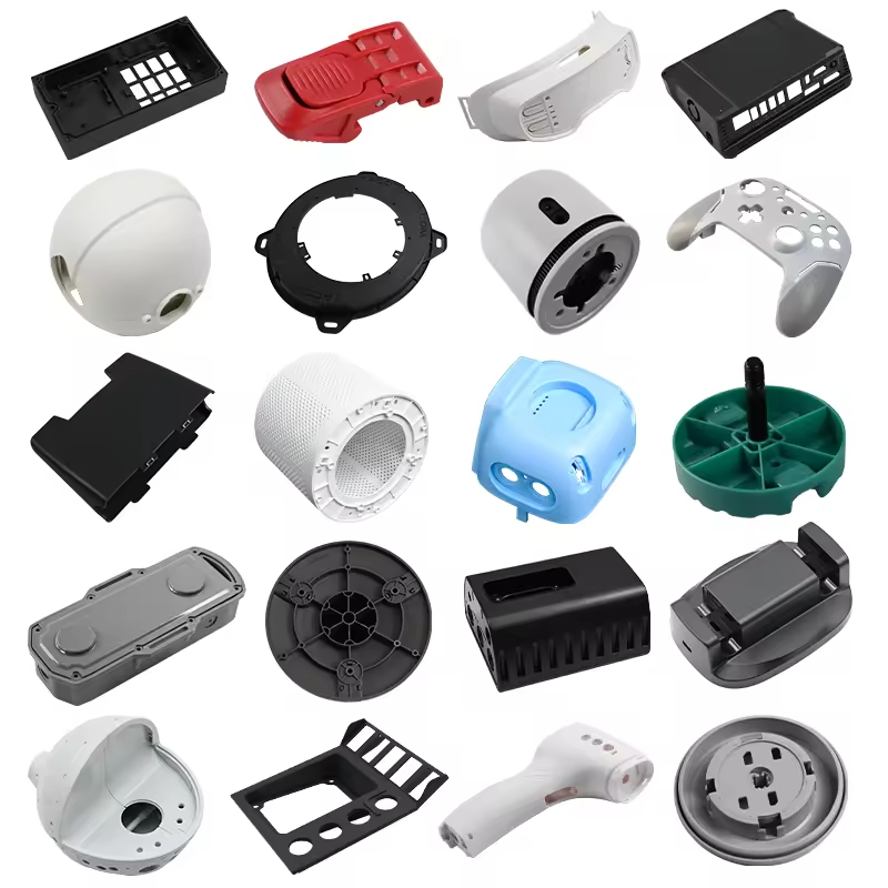
射出成形金型設計入門
射出成形金型の設計は、プラスチック部品製造の成功の基礎です。よく設計された金型は、安定した部品品質、効率的な生産サイクル、長い金型寿命を保証します。このガイドでは、すべてのエンジニアが理解すべき重要な原則について説明します。.
1.均一な肉厚
射出成形において、肉厚を一定に保つことは非常に重要です。ばらつきがあると冷却に差が生じ、反りやヒケ、内部応力の原因となります。.
素材別推奨肉厚
| 素材 | 推奨厚さ (mm) |
|---|---|
| ABS | 1.2 - 3.5 |
| PP | 0.8 - 3.8 |
| PC | 1.0 - 3.8 |
| ナイロン(PA6/PA66) | 0.8 - 3.0 |
| POM | 1.0 - 3.0 |
2.部品解放のためのドラフト角度
抜き勾配は、成形品を金型キャビティからきれいに離型させます。十分な抜き勾配がないと、部品が固着し、欠陥や金型破損の原因となります。.
- 最低喫水: 0.5° - 1° 平滑面用
- 質感のある表面: テクスチャーの深さにより2°~5
- 深い特徴がある: 素材の収縮を補うためにドラフトを上げる
3.適切なリブ・デザイン
4.ゲート位置戦略
ゲートの配置は、充填パターン、溶接線、部品の外観に影響する。考慮してください:
- 流れの長さ: 圧力損失を最小限に抑える
- 溶接線の配置: 非重要分野でのポジション
- 登場: 可能な限り、見えない場所にゲートを隠す
- 部品機能: 荷重のかかる場所の近くにゲートを設けない
5.冷却システム設計
効率的な冷却により、サイクルタイムを短縮し、部品の品質を向上させます。主な考慮事項
- 均一な冷却チャンネル間隔(2~3×チャンネル直径)
- ディープコア用バッフルとバブラー
- 複雑形状のコンフォーマル冷却
- 適切な水流量(乱流体制)
避けるべき一般的な設計ミス
- 適切な機構(リフター、スライド)のないアンダーカット
- 応力集中を引き起こす鋭利な内部コーナー
- 不十分なガス抜きによる焼き付きとショートショット
- 寸法計算における材料の収縮の無視
結論
これらの射出成形金型設計の原則に従うことで、一貫した品質で製造可能な部品が保証されます。製品設計者と金型エンジニアが早期に協力することで、後々コストのかかる修正を防ぐことができます。.
関連リソース
関連リソース
関連リソース
よくあるご質問
『射出成形金型の設計原則 ― ゼロから高品質な金型を構築する』は、どのような場合に役立つのでしょうか?
『射出成形金型の設計原則 — ゼロから高品質な金型を構築する』は、部品の生産量、材料の選定、形状、および再現性の要件が、金型設計や金型製作への投資を正当化する場合に、その価値が発揮されます。.
『射出成形金型の設計原則 ― ゼロから高品質な金型を構築する』において、最も重要な設計要素は何でしょうか?
肉厚、リブ、ボス、抜き勾配、ゲート位置、収縮、パーティングライン、およびエジェクションは、いずれも成形品の品質に影響を与えます。.
金型製作の前に、どのような情報が必要ですか?
サプライヤーは、3Dモデル、材質、予想年間生産数量、外観要件、公差要件、および組み立てや機能試験に関する要件を確認する必要があります。.
『射出成形金型設計の原則――一から高品質な金型を構築する』において、最大のリスクは何でしょうか?
最大のリスクは、実際の用途において、材料の挙動、収縮、流動性、および部品の機能が十分に確認される前に、金型を承認してしまうことです。.
How to Review an Injection Mold Design Before Steel
A good mold design review connects the molded part to the actual production machine, resin, cycle, inspection method and expected tool life. A drawing can look complete while still leaving important decisions open: where the gate will be placed, how air will leave the cavity, how the part will be released, how cooling will reach thick sections and how worn components will be replaced. Before steel is cut, ask for a review that explains these decisions in relation to your part requirements.
Start with the controlled part drawing and mark critical-to-function dimensions, sealing surfaces, assembly datums, cosmetic zones, inserts and areas that cannot show ejector marks or gate vestige. Add the resin grade, filler content, color, annual volume, target cycle and molding machine limits. These inputs determine whether a simple single-cavity tool, a multi-cavity tool, a family mold or a more automated solution is appropriate.
| Design area | Buyer risk | Evidence to request |
|---|---|---|
| Parting line and shutoffs | Flash, mismatch, sealing damage or an unacceptable cosmetic line | Parting-line mark-up, shutoff angles and sample standard |
| Gate and runner | Weld lines, air traps, poor packing, fiber orientation or visible vestige | Gate location, fill direction and runner-balance concept |
| Cooling layout | Long cycle, uneven shrinkage, sink, warpage or local overheating | Cooling circuit drawing and temperature-control assumptions |
| 排出 | Sticking, deformation, drag marks or pin witness on a critical surface | Ejector map, draft review and release-force plan |
| Maintenance access | Long downtime when wear parts or slides need service | Replaceable insert list, spare parts and service access |
Gate, Venting and Cooling Decisions
Gate location should follow the part’s functional and cosmetic priorities. A gate near a thick section may improve packing but can increase sink or vestige. A gate on a cosmetic face may shorten flow length but create an appearance problem. For glass-filled resin, the flow direction can influence stiffness, shrinkage and anisotropy. Multi-cavity tools also need a balanced runner system so each cavity receives a consistent melt history.
Venting is part of the filling design, not a late repair. End-of-fill areas, deep ribs, blind pockets, slides and weld-line regions need a practical escape path for air and gas. Inadequate venting can show up as burn marks, short fill, gloss differences or unstable filling. Ask how vents will be machined, cleaned and protected during maintenance.
Cooling should cover thick bosses, ribs, inserts and areas near the gate while keeping sufficient steel around the cavity. The circuit should be reachable for cleaning and leak checks. Baffles, bubblers or conformal channels may be considered when conventional drilling cannot control temperature. The best choice depends on cycle target, part geometry, steel layout and the value of reducing dimensional variation.
Tool Architecture and Steel Selection
Tool architecture should match volume and resin severity. Prototype and low-volume programs often benefit from accessible inserts and a design that can be changed after the first trial. Higher-volume programs usually need robust cavity details, balanced cooling, reliable automation interfaces and serviceable wear components. For abrasive or corrosive materials, cavity steel, hardness, surface treatment and replaceable gates deserve a documented decision.
| Project condition | Design emphasis | Questions for the quotation |
|---|---|---|
| Prototype or pilot | Fast changes and accessible inserts | Which features can be adjusted after T1? |
| Repeat production | Cycle stability, balance and maintenance access | What shots, cycle and service interval are supported? |
| Abrasive engineering resin | Wear resistance at gates, slides and shutoffs | Which steel and spare inserts are included? |
| Tight cosmetic requirement | Gate, polish, texture, vent and parting-line control | What sample is used for appearance approval? |
Trial, Inspection and Tool Acceptance
A mold should be accepted against an agreed trial plan, not only because the machine produces a part. Record resin grade and lot, machine, mold temperature, melt temperature, injection profile, holding conditions, cycle and cavity identification. Review short shots, flash, sink, burn marks, weld lines, ejection, warpage and dimensions. For multi-cavity tools, inspect cavity-to-cavity variation instead of relying on one representative part.
Before production release, request the approved mold drawing, steel and component list, cooling and pneumatic diagrams, cavity identification, spare-parts list, maintenance instructions and dimensional report. Critical features should be measured with the agreed datum and conditioning state. If a dimension is affected by moisture or temperature, define when the measurement is taken. We can support DFM review, mold design, fabrication, sampling and corrective changes as one connected project.
For an RFQ, send CAD, controlled drawing, resin data, volume, target cycle, machine information, cosmetic zones, critical dimensions, inserts, post-molding assembly and required tests. A complete input package allows a mold supplier to price the actual risk rather than adding broad assumptions to the quotation.